11
EN
Date: 10-16-2014
Operating Guide
Informer Compact UPS Series
About the device
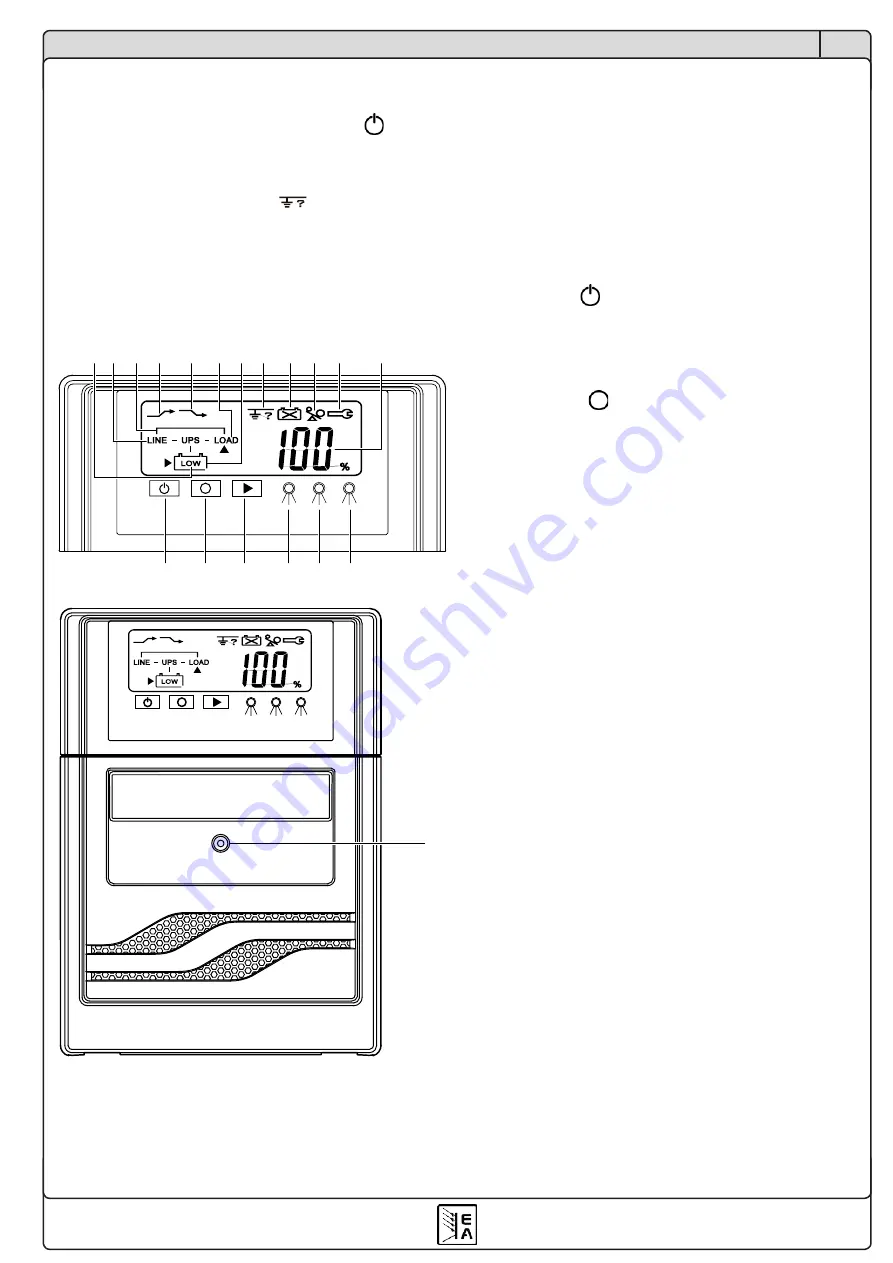
3. Front panel elements
1 - LED/Symbol „Mains OK“
Mains operation is the normal operation of the UPS, if
mains voltage is present. The output voltage is provided
to the output via a transformer and is held constant.
2 - LED/Symbol „Error“
Indicates errors like overload, short-circuit at the output
or other errors. Is accompanied by an audible alarm.
3 - Button ON / SILENCE
This button is used to switch the UPS on by pressing it
>4s, as well as to mute the audible alarm (press >2s)
until a new error occurs.
4 - Button OFF
Is used to switch the UPS off (press >4s).
5 - Symbol „Battery replacement“
Indicates an insufficient capacity and a probably bad
condition of the batteries. Once this is indicated, they
should be maintained, i.e. replaced.
6 - LED/Symbol „Battery operation“
Indicates that the battery operation is active, because of
mains loss or because the mains voltage has dropped
by more than 25%.
In case the LED is flashing, while the UPS is switched
off, this indicates that the batteries are charged.
7 - Screw for battery cover
8 - Symbol „Low battery“
Indicates a low battery level and warns against immi-
nent shutdown of the UPS.
9 - Flow chart
Shows symbolically the current flow inside the UPS
and thereby the operation modes.
10 - Symbol „Mains low“
Indicates that the mains voltage has dropped down by
-9% or more. The UPS compensates this with +15%
voltage increase (boost).
11 - Symbol „Mains high“
Indicates, that the mains voltage is too high (9% or
more). The UPS will then compensate this by -15%
(buck).
12- Symbol LOAD
Indicates voltage is present at the output.
2.4 First time operation
After all necessary connections have been made,
switch the UPS on by pressing the button for >4s.
The display will light up and the green LED should
indicate mains supply is present. The display shows
the load level in %, as well as the operation mode in
the little flow chart.
In case the
symbol is blinking,
pull the mains cord (at the mains socket) and plug it in
again, rotated by 180°.
The device is now ready to work.
IN
OUT
USB
RS232
IN
OUT
USB
RS232
17 18 19 20 21
23
22
24
25
17 18 19 20 21
23
22
24
25
8 1 9 10 11 12
13
14
6
5
2
15
3
16
4
6 2 1
DIP Switch
Setting
3 2 1
VOLTAGE=220V
VOLTAGE=230V
VOLTAGE=240V
VOLTAGE=50Hz
VOLTAGE=60Hz
FUNCTION
7
3 100 06
3 100 20
3 100 07
3 100 08
1. Led für Stromnetzanschluss
2. Alarmleuchte (Led)
3. Taste ON
4. Taste OFF
5. Batterie auswechseln
6. Led Batteriebetrieb
7. Schraube für Batteriedeckel
8. Anzeige für erschöpfte Batterien
9. Bypass-Anzeige
10. Anzeige Stromnetzspannung zu schwach
11. Anzeige Stromnetzspannung zu stark
12. Anzeige USV-Ausgang vorhanden
13. Anzeige falsche Erdung
14. Überlastanzeige
15. Anzeige Prozent der Batterieladung
16. Wahltaste Anzeige der Batterieladung
17. Port RJ45
18. Dip-Schalter
19. Steckerbuchse für Schnittstelle USB
20. Steckerbuchse für Serienschnittstelle RS232
21. Interne CPU-Reset-Taste
22. Ausgangsschalter
23. Ausgänge
24. Eingangs-Schmelzsicherung
25. Steckerbuchse Netzeingang
AChTUNg
Die USV kann nicht im Normalbetrieb eingeschaltet werden,
wenn beide Dip-Schalter DIP-2 und DIP-3 auf ON geschaltet sind.
IN
OUT
USB
RS232
IN
OUT
USB
RS232
17 18 19 20 21
23
22
24
25
17 18 19 20 21
23
22
24
25
8 1 9 10 11 12
13
14
6
5
2
15
3
16
4
6 2 1
DIP Switch
Setting
3 2 1
VOLTAGE=220V
VOLTAGE=230V
VOLTAGE=240V
VOLTAGE=50Hz
VOLTAGE=60Hz
FUNCTION
7
3 100 06
3 100 20
3 100 07
3 100 08
1. Led für Stromnetzanschluss
2. Alarmleuchte (Led)
3. Taste ON
4. Taste OFF
5. Batterie auswechseln
6. Led Batteriebetrieb
7. Schraube für Batteriedeckel
8. Anzeige für erschöpfte Batterien
9. Bypass-Anzeige
10. Anzeige Stromnetzspannung zu schwach
11. Anzeige Stromnetzspannung zu stark
12. Anzeige USV-Ausgang vorhanden
13. Anzeige falsche Erdung
14. Überlastanzeige
15. Anzeige Prozent der Batterieladung
16. Wahltaste Anzeige der Batterieladung
17. Port RJ45
18. Dip-Schalter
19. Steckerbuchse für Schnittstelle USB
20. Steckerbuchse für Serienschnittstelle RS232
21. Interne CPU-Reset-Taste
22. Ausgangsschalter
23. Ausgänge
24. Eingangs-Schmelzsicherung
25. Steckerbuchse Netzeingang
AChTUNg
Die USV kann nicht im Normalbetrieb eingeschaltet werden,
wenn beide Dip-Schalter DIP-2 und DIP-3 auf ON geschaltet sind.


