PANEL LAYOUT AND CONNECTORS
6
REAR CONNECTORS
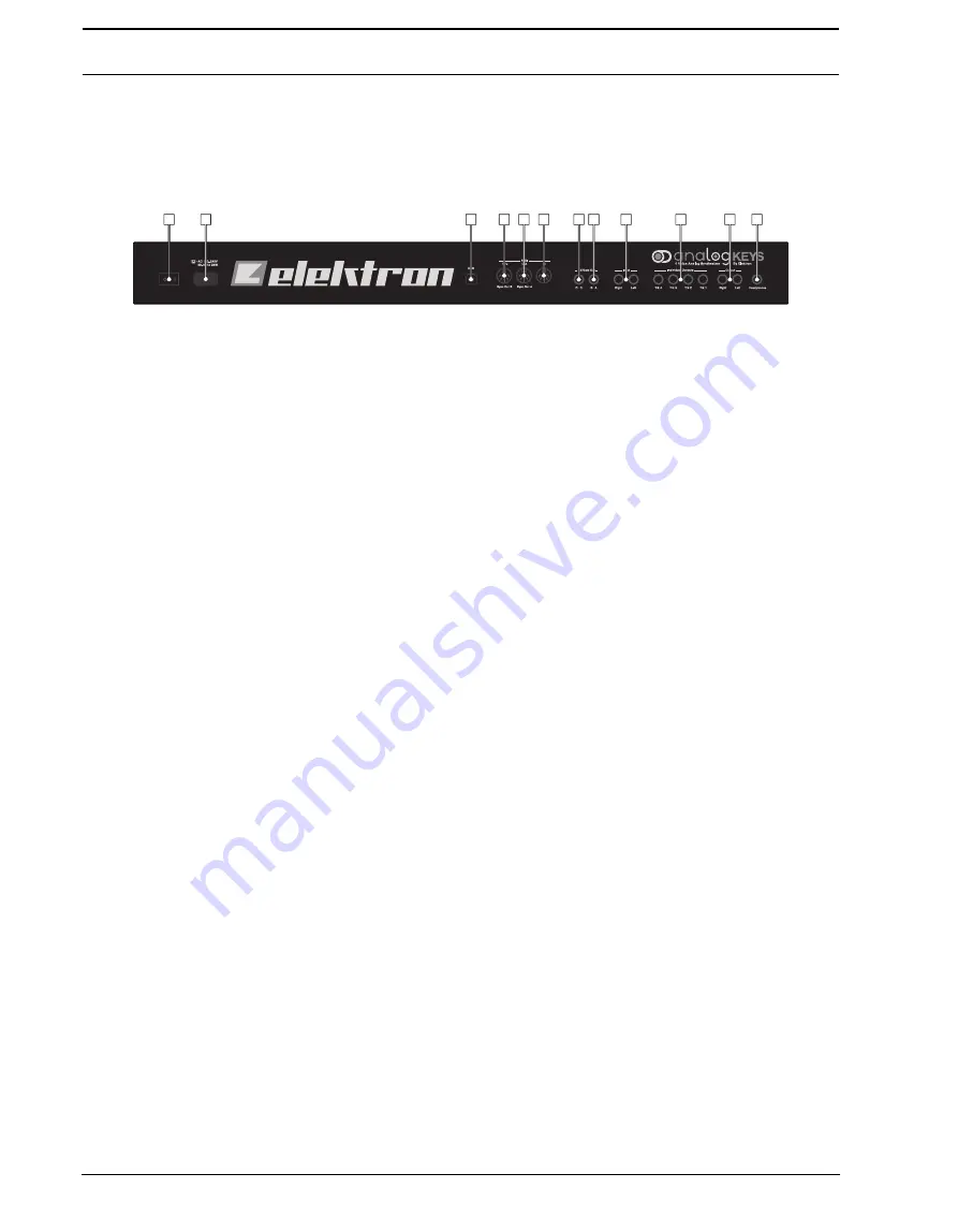
The Analog Keys Rear Connectors.
1.
Power on/off switch.
2.
Power in (100-250 V AC, 50-60 Hz).
Use the included C7 power cable, or equivalent, connected to a
power outlet.
3.
Full-speed USB 2.0 Connection.
Connect using the included A to B USB 2.0 connector cable to a com-
puter host.
4.
MIDI Thru.
Use standard MIDI cable to connect another MIDI unit in chain. Duplicates incoming MIDI In
data stream.
5.
MIDI Out.
Use standard MIDI cable to connect to MIDI In of an external MIDI unit in order to control it.
6.
MIDI In.
Use standard MIDI cable to connect MIDI Out of an external MIDI unit in order for it to control
Analog Keys.
7.
CV outputs C and D.
Connect to external synth with CV inputs. Use either standard 1/4” mono phone plug
or 1/4” insert/Y cable.
8.
CV outputs A and B.
Same recommended connector as above.
9.
Audio input L/R.
Use standard 1/4” mono phone plug to input sound from other synthesizers or mixers.
10. Individual stereo outputs Track 1-4.
Use 1/4” insert/Y cable in order to access both left and right chan-
nels.
11. Main Out L/R.
Use either 1/4” mono phone plug (unbalanced connection) or 1/4” stereo (Tip/Ring/Sleeve)
phone plug (balanced connection).
12. Headphones Output.
Connect standard headphones with 1/4” stereo phone plug.
CONNECTING THE UNIT
Make sure you place the Analog Keys on a stable support, such as a sturdy table with sufficient cable space or
a synth stand capable of a 10 kg load.
1.
Before you connect the Analog Keys to other equipment, make sure all units are switched off.
2.
Plug the included AC cable into a power outlet and the Analog Keys.
3.
Connect the main out L/R from the Analog Keys to your mixer or amplifier.
4.
If MIDI control is desired, connect the MIDI OUT port of the device you wish send data from to the MIDI IN
port of the Analog Keys. The MIDI THRU port duplicates the data arriving at the MIDI IN port. It is used for
chaining several MIDI units together.
5.
Switch on all units. Switch on the unit by pressing the Power rocker switch located at the back of the unit.
Before restarting the unit, wait 2 seconds after the LCD backlight goes out.
Power
2
1
3
4
5
6
7
8
9
10
11
12
Summary of Contents for Analog Four
Page 1: ......
Page 4: ......
Page 11: ...ANALOG KEYS BACKGROUND 3 ...
Page 90: ...CREDITS AND CONTACT INFORMATION 82 ...
Page 102: ...B 6 Appendix B FX TRACK PARAMETERS ...
Page 122: ...D 14 Appendix D MIDI ...
Page 124: ...E 2 Appendix E ANALOG KEYS ARCHITECTURE ...
Page 128: ...4 INDEX ...
Page 129: ......
Page 130: ......


