background image

CHAINS AND SONGS

48

it will play through its chain of patterns once, then stop. If the scratch pad row has been moved within the song, 
it will play the following song row. The song row playing is shown in the lower left corner of the LCD screen.

SONG EDIT MENU

Songs are created in the SONG EDIT menu, which is accessed by pressing 

[FUNCTION]

 + 

[SONG MODE]

.

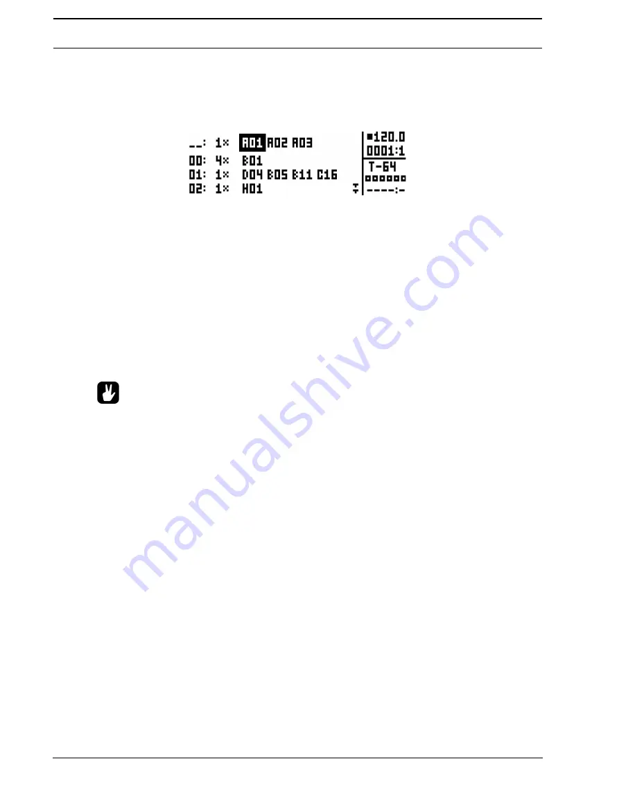
Songs are played row by row, starting from the top and moving towards the bottom. If a song row contains a 
chain, all patterns in the chain will play before the song play position moves to the next row. The song play posi-
tion is indicated by inverted pattern number graphics. In the top right corner of the LCD screen the BPM and the 
amount of played bars and beats is shown.

To navigate between song rows as well as patterns assigned to the song rows, use the 

[ARROW]

 keys. When 

the song cursor highlights a pattern position, the pattern number becomes enclosed by a square. When the 
song cursor is placed before or after a pattern, it will form a thin line. 

To start playing a Song from the beginning, double-press 

[STOP]

. The song play position will automatically be 

moved to the first pattern of the first song row. Songs can, however, start playing from any pattern position. High-
light a pattern position by moving the song cursor using the 

[ARROW]

 keys. Press 

[YES/SAVE]

 to select this 

position. The graphics will become inverted, indicating this is the song play position. Press 

[PLAY]

 to start play-

ing the Song from this position.

Copy, paste and clear commands can be executed on the song rows.

ADDING SONG ROWS AND ASSIGNING PATTERNS AND CHAINS

Press 

[FUNCTION]

 + 

[YES/SAVE]

 to add a song row. The new song row will be inserted below the row on 

which the cursor is, and the pattern A01 will automatically be assigned to the new row. To assign another pattern 
to the song row, use the 

[ARROW]

 keys to move the song cursor so the pattern assigned to the row becomes 

highlighted and then press a 

[BANK X/X]

 key + a 

[TRIG]

 key. In general, the pattern assigning procedure is the 

same as when selecting a pattern, covered in the section “SELECTING A PATTERN” on page 32.

To add a chain to a song row, select a song row and press the 

[RIGHT]

 arrow key. The song cursor will move 

from the pattern position and form a thin, standing line. Press a 

[BANK X/X]

 key + a 

[TRIG]

 key to select the 

pattern that will be added to the chain.

Remove a pattern in a chain by highlighting it with the song cursor and pressing 

[FUNCTION]

 + 

[NO/RELOAD]

.

If a song row contains a chain, individual patterns can be rearranged in the chain. Select the pattern by highlight-
ing it with the song cursor and press 

[FUNCTION]

 + 

[LEFT]

/

[RIGHT]

.

Move a song row up or down in the song by moving the song cursor to the song row and pressing 

[FUNCTION]


[UP]

/

[DOWN]

. Note that the scratch pad row “_ _:” can be moved up or down in the list in the same way. The 

position of the scratch pad row is important, because it determines where the new song row will be located, 
when a new chain (and a new scratch pad row) is created outside of the SONG EDIT menu. The new song row 
will be inserted above the new scratch pad row, and it will have the same number as the song row below the pre-
vious scratch pad row.

Erase an entire song row, one pattern at a time, by repeatedly pressing 

[FUNCTION]

 + 

[NO/RELOAD]

.

ADDING REPEATS, MUTES AND TRANSPOSE INFORMATION

Various extra information can be entered for song rows and pattern or patterns assigned to the song rows.

Summary of Contents for Analog Four

Page 1: ......

Page 2: ... no guarantee that interference will not occur in a particular installation If this equipment does cause harmful interference to radio or television reception which can be determined by turning the equipment off and on the user is encouraged to try to correct the interference by one or more of the following measures Reorient or relocate the receiving antenna Increase the separation between the equ...

Page 3: ...re you place the unit on a stable surface before use 5 Connect to an easily accessible power outlet close to the unit 6 In the EU only use CE approved power cords 7 When transporting the unit preferably use accessories rec ommended by the manufacturer or the box and padding the unit originally shipped with 8 Do not install near any heat sources such as radiators heat registers stoves or any other ...

Page 4: ......

Page 5: ...9 SONG 9 CHAINS 9 GLOBAL 9 ABOUT THE TRACK TYPES 9 THE SYNTH TRACKS 9 THE FX TRACK 9 THE CV TRACK 9 EDITING THE TRACKS 9 THE USER INTERFACE 10 PARAMETER EDITING 10 QUICK PARAMETER EDITING 10 PARAMETER VALUE JUMP 10 QUICK SCROLLING 11 COPY CLEAR AND PASTE 11 ONE HANDED OPERATION 11 THE NAMING MENU 11 POP UP MENU NAMING 11 OVERBRIDGE 12 QUICK START 13 PLAYING THE FACTORY PRESETS 13 PERFORMANCE MODE ...

Page 6: ...TING 31 THE SEQUENCER 32 BASIC PATTERN OPERATIONS 32 SELECTING A PATTERN 32 PATTERN CONTROL 33 TEMPO 33 PATTERN MODES 33 EDITING A PATTERN 34 TRIG TYPES 34 GRID RECORDING MODE 34 LIVE RECORDING MODE 34 TRACK MENU 35 PATTERN MENU 35 ARPEGGIATOR 36 ARPEGGIATOR SETUP 37 NOTE MENU 37 NOTES SETUP 38 CLICK TRACK 39 SCALE MENU 39 NORMAL MODE 39 ADVANCED MODE 40 SEQUENCER FEATURES 40 PARAMETER LOCKS 40 SO...

Page 7: ...ECEIVE 61 SYSTEM 62 USB CONFIG 62 OS UPGRADE 62 FORMAT DRIVE 63 CALIBRATION 63 EARLY STARTUP MENU 64 TEST MODE 64 EMPTY RESET 64 FACTORY RESET 64 OS UPGRADE 64 MORE ON OSCILLATORS FILTERS AND ENVELOPES 65 OSCILLATORS 65 OTHER OSCILLATOR WAVEFORM SELECTIONS 66 FILTERS 67 4 POLE LADDER FILTER 67 2 POLE MULTI MODE FILTER 67 ENVELOPES 68 SETUP EXAMPLES 69 ANALOG KEYS CONTROL OF AN EXTERNAL ANALOG SYNT...

Page 8: ...EFERENCE MANUAL 81 CONTACT INFORMATION 81 ELEKTRON WEBSITE 81 DELIVERY ADDRESS 81 TELEPHONE 81 APPENDIX A SYNTH TRACK PARAMETERS OSCILLATOR 1 1 OSCILLATOR 2 2 FILTERS 3 AMPLITUDE 4 ENVELOPES 5 LFO 6 APPENDIX B FX TRACK PARAMETERS EXTERNAL IN 1 WIDESHIFT CHORUS 2 SATURATOR DELAY 3 SUPERVOID REVERB 4 FX LFO 5 APPENDIX C CV TRACK PARAMETERS CV A D 1 CV ENVELOPES 5 CV LFO 6 APPENDIX D MIDI PERFORMANCE...

Page 9: ...ts For instance the button labeled function on the main panel is written FUNCTION Menu names are written in upper case The OSC 1 menu is an example of that Parameter names and certain menu options where settings can be made or actions performed are written in bold upper case style VOL for example Upper case style is used for parameter setting alternatives for example OFF and for certain menu setti...

Page 10: ...brilliant effects and the same capable Elektron step sequencer Added were ele ments aimed at making it more suited for the stage The keyboard the joystick the dedicated buttons the indi vidual outputs and all the other design choices are results of this ambition The Analog Keys has in other words been conceived with full focus on playability We are incredibly proud of the Analog Keys and we believ...

Page 11: ...ANALOG KEYS BACKGROUND 3 ...

Page 12: ... tap the tempo 10 YES SAVE key Used for entering sub menus and for confirming choices 11 NO RELOAD key Used for exiting an active menu and backing one step 12 The LCD window 13 The ARROW keys Used for menu navigation They are called UP DOWN LEFT and RIGHT 14 PERFORMANCE enters PERFORMANCE mode 15 ARP key Controls for the arpeggiator of the active track are found here 16 NOTE key Note settings for ...

Page 13: ...bank A or E The secondary function opens the TRIG MUTE menu 32 KEYBOARD spans three octaves and has 37 semi weighted after touch and velocity sensitive keys 33 OCTAVE UP shifts the KEYBOARD range up one octave 34 OCTAVE DOWN shifts the KEYBOARD range down one octave 35 OCTAVE LEDs shows the octave transposition for the KEYBOARD 36 JOYSTICK for up to 15 custom assigned parameters such as pitch bend...

Page 14: ...s Track 1 4 Use 1 4 insert Y cable in order to access both left and right chan nels 11 Main Out L R Use either 1 4 mono phone plug unbalanced connection or 1 4 stereo Tip Ring Sleeve phone plug balanced connection 12 Headphones Output Connect standard headphones with 1 4 stereo phone plug CONNECTING THE UNIT Make sure you place the Analog Keys on a stable support such as a sturdy table with suffic...

Page 15: ...udio outputs is also completely analog The digital send effects are parallel to the main audio path and the wet signals from the digital send effects are mixed with the dry analog signal before the main output stage ABOUT THE OSCILLATORS AND FILTERS The oscillators are designed and built from scratch in order to obtain a lush sound and provide an array of con trol features The ladder filter utiliz...

Page 16: ... Keys always retains the active working state the active project even when switched off However it must be manually saved in a project slot before another project is loaded or it will be lost Projects are saved loaded et cetera in the GLOBAL menu Read more about projects in the sec tion PROJECTS on page 16 KIT Kits contain four Sounds one for each synth track and settings for the FX and CV tracks ...

Page 17: ...e load and manage projects handle SysEx data and perform OS upgrades It also contains general settings for the synth and sequencer as well as MIDI and CV configurations Four global slots are available for every project each with its own individual settings Read more about the global settings in the section GLOBAL MENU on page 50 ABOUT THE TRACK TYPES THE SYNTH TRACKS The synth tracks consist of tr...

Page 18: ... the scratch pad row is active 7 The currently active kit When turning a DATA ENTRY knob the full name of the parameter being adjusted is shown here All windows can be closed using the NO RELOAD key Buttons or knobs not used by an active menu retain their original function For example the TEMPO menu makes use of the SOUND SELECTION wheel but you can still use the DATA ENTRY knobs to control the pa...

Page 19: ...o play the KEYBOARD or tweak sounds With the FUNCTION key in the vicinity of the TRACK keys one handed track muting is possible As is one handed transpose locking copy clear and paste commands pattern play mode change and more THE NAMING MENU The naming procedure is identical for the various naming menus that exist The LEFT and RIGHT arrow keys are used to navigate between the letters Turning the ...

Page 20: ...hine State Total Recall functionality All that is required is an Elektron Analog instrument a USB cable a computer running Overbridge and a DAW If you want to hook up multiple machines to a computer we suggest acquiring the Elektron Overhub a Multi TT hub tailored for Overbridge use Overbridge is available as a complimentary download from the Elektron webpage Please read the Overbridge manual also...

Page 21: ...bs to control several PARAMETER page parameters at once This is called a parameter macro 1 Make sure a pattern is playing 2 Press the PERFORMANCE key to access PERFORMANCE mode 3 Turn the DATA ENTRY knobs and hear how the sound of the pattern changes ADJUSTING PARAMETERS Each track contains six PARAMETER pages Parameters affecting the sound of the track are found on these pages 1 Make sure a patte...

Page 22: ...nal JOYSTICK Its default functionality is pitch bend in the sideways direction modulation in the upward direction and breath control in the downward direction Press SOUND and select SOUND SETTINGS to customize the JOYSTICK functionality and the parameters it will control See page 29 for further details OCTAVE SHIFT The two keys OCTAVE DOWN and OCTAVE UP shift the playable keyboard range a whole oc...

Page 23: ...The red LED above each affected KEYBOARD key will be lit for all held notes You can repeat this and hold notes on any of the tracks without releasing the already held notes You can also hold multi mapped sounds or other functions and hold notes on external synths without releasing notes already held on the KEYBOARD All notes held will remain so until the key of the held note is pressed a second ti...

Page 24: ...the unit switch it on again and have everything sound as it did prior to the power cycling Please note that changes are not automatically written to the Drive To store the active working state of the project to a Drive slot the project needs to be saved manually PROJECT MENU Projects are managed in the PROJECT menu located in the GLOBAL menu Open the GLOBAL menu by pressing FUNCTION SONG Scroll th...

Page 25: ...ots DELETE removes the project from the slot RENAME opens a screen where you can rename the project file LOAD FROM loads the selected project This will overwrite the active project SAVE TO saves the active project to the selected slot TOGGLE toggles write protection on or off Write protected projects can not be overwritten renamed or erased A write protected project is indicated by a lock symbol M...

Page 26: ...LEVEL settings for the Synth and FX tracks PERFORMANCE mode parameter settings Polyphony settings A Sound contains Settings for the PARAMETER pages of a synth track The LCD graphics in the left part of the screen shows the name of the currently active kit When the TRACK keys are pressed this information will briefly change to reflect the name of the track In the case of the synth tracks the name o...

Page 27: ...ngs can be saved as a kit The saved kit will be linked to the active pattern YES SAVE KIT offers a short cut to this command When this menu is opened the kit list will appear The active kit is indicated by inverted graphics Select the slot to which the kit will be saved by using the ARROW keys or the SOUND SELECTION wheel Press YES SAVE to save to the selected slot The NAMING menu covered on page ...

Page 28: ...status of the tracks PERFORMANCE SETUP The ten performance macros available in the PERFORMANCE mode are set up in the PERFORMANCE SETUP menu Access this menu by pressing FUNCTION PERFORMANCE The collection of all ten performance macros can be copied cleared and pasted while in this menu PERFORMANCE CONFIGURE is where parameters are assigned to the performance mac ros After selecting this option th...

Page 29: ...ffset of 63 to the OSC1 PITCH parameter Conversely turning the parameter macro knob to 64 will introduce a parameter value offset of 64 to the OSC1 PITCH parameter Use parameter macros to affect the most relevant parameters when playing live By carefully set ting up parameter macros you might find that you don t have to leave this mode at all during your live set PERFORMANCE RENAME allows performa...

Page 30: ...g the YES SAVE button To activate deactivate voice 1 4 directly press TRIG key 1 through 4 When in the POLY CONFIG menu the red LEDs above TRIG key 1 4 on the front panel will be half bright When a voice is activated the corresponding LED will be full bright Voices that are not set to be poly ena bled will be dedicated monophonic voices for their corresponding tracks These will never be used for p...

Page 31: ...et the width of the pan spread 0 127 around the center point of the unison sound Use the LEFT and RIGHT arrow keys to set the value If no free voice is found the least recently used voice is stolen and used for the played note See illustration on page 25 This applies to all allocation methods described above VOICE ROUTING Set custom voice routing by accessing VOICE ROUTING found at the bottom posi...

Page 32: ...CEB VOICEC VOICEB VOICEA B C D VOICEA D VOICEA PLAYEDNOTE ASSIGNEDVOICE BEGINNINGOFNOTE ENDOFNOTE SHOWNASPLAYEDFROMTRACK1 POLYPHONICVOICEALLOCATIONMETHOD ROTATE C D D F VOICEA B C D PLAYEDNOTE ASSIGNEDVOICE BEGINNINGOFNOTE ENDOFNOTE C D D F VOICED VOICEC VOICEB D VOICEA VOICEA ...

Page 33: ... D F C D D F VOICED VOICEC VOICEB D VOICEB VOICEA B C D VOICEA PLAYEDNOTE ASSIGNEDVOICE BEGINNINGOFNOTE ENDOFNOTE VOICESTEALING C D D F G C VOICESTOLENBYGNOTE D D F G VOICEC VOICED VOICEB VOICEA B C D VOICEA VOICEA PLAYEDNOTE ASSIGNEDVOICE BEGINNINGOFNOTE ENDOFNOTE ...

Page 34: ...the RIGHT arrow key to exit the menu POOL lists Sounds available in the Sound pool of the active project The command is only available when browsing the Drive Sound library DRIVE lists Sounds available on the Drive Sound library The command is only available when browsing the Sound pool of the active project SORT ABC sorts the Sounds in alphabetical order The command is only available when Sounds ...

Page 35: ...art of the active kit COPY TO POOL copies the selected Sounds to the first free slots of the active project Sound pool This command is only available when browsing the Drive Sound library COPY TO DRIVE copies the selected Sounds to the first free slots of the Drive Sound library This command is only available when browsing the Sound pool of the active project STORE TRACK SOUND saves the active tra...

Page 36: ... Use the UP DOWN arrow keys or the SOUND SELECTION wheel to scroll in the menu Use the LEFT RIGHT arrow keys to change the settings The parameters assignable to the controllers modulation wheel breath controller et cet era will vary according to the type of track that is active Synth FX or CV OSCILLATOR DRIFT will when activated introduce a very subtle pitch drift to the oscillators which can incr...

Page 37: ...e these messages will affect the parameters assigned in this menu Open the menu by pressing YES SAVE Setting up the parameters works in the same way as setting up performance macros covered on page 20 MODULATION WHEEL gives access to a menu where up to 5 PARAMETER page parame ters can be assigned to the MIDI mod wheel command CC 1 Open the menu by pressing YES SAVE Setting up the parameters works ...

Page 38: ...red on page 53 EDITING A SOUND To edit a Sound first select one of the synth tracks by pressing TRACK keys 1 4 The Sound of the active synth track is the one that will be edited The overall volume level of the active track is adjusted with the LEVEL knob In the PERFORMANCE MIXER menu all track levels are visible at the same time and can be edited using the DATA ENTRY knobs Read more on page 21 Sou...

Page 39: ...pages CV A controls the signal sent from the CV A output CV B controls the signal sent from the CV B output CV C controls the signal sent from the CV C output CV D controls the signal sent from the CV D output ENV offers two freely assignable envelopes which can be used to control the CV track param eters LFO offers two freely assignable LFOs which can be used to control the CV track parameters TR...

Page 40: ...press TRIG key 5 Patterns containing data are indicated by half bright red TRIG LEDs The currently active pattern is indicated by a full bright red TRIG LED When you select a pattern containing no data the kit of the previous pattern will be preliminarily selected and the kit number will start flashing on the LCD screen to draw attention to the fact that the kit is not yet decisively linked to the...

Page 41: ...ntinuing tapping the average tempo will keep on updating The tempo can temporarily be shifted up or down by 10 by pressing the LEFT or RIGHT arrow keys When the key is released the BPM will revert back to the original setting When in the TEMPO menu holding FUNCTION while turning the SOUND SELECTION wheel will not change the tempo to the selected value until the FUNCTION key is released Tempo shift...

Page 42: ...er While in GRID RECORDING mode hold down FUNCTION while pressing the LEFT or RIGHT arrow keys to perform the trig shift Preview a note trig complete with its parameter locks by pressing TRIG a key on the KEY BOARD LIVE RECORDING MODE LIVE RECORDING mode is the second method of adding trigs to the tracks In this recording mode the KEY BOARD or an external MIDI keyboard connected to Analog Keys can...

Page 43: ...d on the results are favorable and you want to keep on working with the track while having the ability to revert it to a specific saved state The SAVE TRACK command makes this possible When reloading the track it will not be reloaded to its original pattern auto saved state but to the manually saved state Press YES SAVE TRACK for a short cut to the SAVE TRACK command PATTERN MENU In the PATTERN me...

Page 44: ...rst octave range will be played randomly and once all notes have been played all the notes of the second octave will be played in a new random order RND will randomize the playback of the arpeggiated notes PLY will arpeggiate a complete chord POLYPHONY must be activated see page 22 in the same way an individual note is arpeggiated in TRU mode SPD sets the speed of the arpeggiator It is synchronize...

Page 45: ...ing NOTE NOTE menu set tings are a part of the pattern they are not stored together with kits The parameter settings seen in the NOTE menu settings are the default settings when placing trigs on the sequencer Entering three note trigs changing for example the note length parameter and then entering three more note trigs will thus make the last three note trigs share a different note length compare...

Page 46: ...D SELECTION wheel Change settings with the LEFT RIGHT arrow keys GLOBAL QUANTIZE will affect all micro timed trigs of all tracks The higher the quantize value the more all micro timed trigs will be quantized TRK QUANTIZE will affect all micro timed trigs of the active track The higher the quantize value the more all micro timed trigs will be quantized TRK KEY SCALE sets the key scale of the track ...

Page 47: ... adjust the different settings and to select between the two modes The SOUND SELECTION wheel can also be used to adjust the settings NORMAL MODE This is the default mode In this mode all tracks of the pattern share the same length and time signature This screen will appear when the NORMAL setting is active The first two settings control the step length of the pattern The leftmost number selects th...

Page 48: ...hout ever being restarted Note that this setting also affects for how long the active pattern will play before a chained pattern will start playing This can be overridden by the CHNG parameter CHNG controls for how long the active pattern will play before a cued or chained pattern will begin to play This setting is important when for example LEN is set to INF If no CHNG setting is made the pattern...

Page 49: ... locks will however not be erased Remove specific parameter locks in real time by pressing NO RELOAD while pressing the DATA ENTRY knob corresponding to the parameter that will be removed Up to 128 different parameters can be locked in a pattern A parameter counts as one 1 locked parameter no matter how many trigs that lock it If for example the cutoff parameter of the ladder filter of synth track...

Page 50: ...rue when FILL is not PRE is true if the most recently evaluated note condition on the same track was true PRE is true when PRE is not NEI is true if the most recently evaluated note condition on the neighbour track the track above the one being edited was true NEI is true when NEI is not 1ST is true the first pattern cycle until the pattern has looped 1ST is true when 1ST is not X is a probability...

Page 51: ... of a bass line track could for example be muted to build suspense ACCENT Adding accent trigs is useful for quickly changing the volume and filter envelope behavior or accentuation for chosen steps of a track Accent level is a destination for modulation which means it can be affected by for example LFOs Open the ACCENT menu by pressing FUNCTION BANK B F Select the track that will be affected by pr...

Page 52: ...ep as the trig If that is the case the BANK C G LED will light up PARAMETER SLIDE The PARAMETER SLIDE menu makes it possible for the parameter values of two separate note trigs or trigless locks of a track to slide between each other Open the menu by pressing FUNCTION BANK D H When this menu is active and TRIG keys are pressed slide trigs will be placed on the sequencer For a parameter value to sl...

Page 53: ...posed note trigs will be permanently altered If FUNCTION TRANSPOSE are pressed the transpose lock functionality will be activated Transpose lock is indicated by a full bright TRANSPOSE LED When this function is activated the TRANSPOSE key will act as if constantly pressed enabling one handed transpositions when pressing the KEYBOARD keys Please note that when transpose lock is activated the KEYBOA...

Page 54: ...r TRIG key and pressing STOP Clear trig locks by holding one or more trigs and press PLAY QUICK SAVE AND RELOAD COMMANDS Kits Sounds tracks patterns and songs can instantly be saved and reloaded When reloading settings will revert to their saved state To quick save a kit press YES SAVE KIT This command is the same as the SAVE KIT command found in the KIT menu covered on page 19 To quick save the t...

Page 55: ...ore the pattern located after the cursor If the cursor is highlight ing a pattern and a new pattern is selected the highlighted pattern will be replaced When activating CHAIN mode the patterns in the chain will be played in sequence The chain will be looped once the final pattern of the chain has played To create chains in quick mode press and hold BANK X X and then press the TRIG key for the patt...

Page 56: ...ON YES SAVE to add a song row The new song row will be inserted below the row on which the cursor is and the pattern A01 will automatically be assigned to the new row To assign another pattern to the song row use the ARROW keys to move the song cursor so the pattern assigned to the row becomes highlighted and then press a BANK X X key a TRIG key In general the pattern assigning procedure is the sa...

Page 57: ...G MODE TRACK or CHAIN MODE TRACK Transpose a pattern by highlighting it with the song cursor and pressing TRANSPOSE a KEYBOARD key A song transpose works like a track transpose albeit automated The track transpose functionality is covered on page 45 SONG MENU In the SONG menu songs can be saved loaded renamed et cetera Access the menu by pressing FUNCTION SONG RELOAD will reload the active song It...

Page 58: ...TS on page 16 GLOBAL SLOT Selects which of the four Global slots to use Select the active slot by using the LEFT RIGHT arrow keys Press YES SAVE to confirm the selection All changes made to a Global slot are automatically saved A slot stores the current configuration of the synth sequencer CV and MIDI settings All changes made to a Global slot are automatically saved SYNTH MASTER TUNE The Analog K...

Page 59: ...Keys receives and sends MIDI clock and transport commands Change settings by using the LEFT RIGHT arrow keys CLOCK RECEIVE will when active make Analog Keys respond to MIDI clock sent from exter nal devices CLOCK SEND will when active make Analog Keys transmit MIDI clock TRANSPORT RECEIVE will when active make Analog Keys respond to system realtime mes sages like play stop continue and song positi...

Page 60: ... are put in a ready to start mode In this mode the synced unit will start directly when the sequencer starts When in this mode an external unit for example a TB 303 cannot be programmed Exit the ready to start mode by pressing STOP once THRU PORT FUNCTIONALITY selects what type of signal the MIDI THRU port will send The same settings as for OUT PORT FUNCTIONALITY exist INPUT FROM selects the sourc...

Page 61: ...e unmute will send MIDI CC NRPN messages or not When set to INT no MIDI data will be sent When set to INT EXT messages will be sent internally as well as externally When set to EXT messages will only be sent externally RECEIVE NOTES will when active make it possible to play Analog Keys using an external MIDI keyboard RECEIVE CC NRPN will when active make it possible to control Analog Keys paramete...

Page 62: ...dditionally the internal multi map trigs can be recorded with the Analog Keys sequencer At most one unique function may be mapped to each of the 128 keys of the entire MIDI keyboard range One multi map setting is stored for each global slot which means 4 different keyboard maps per project can be used Press FUNCTION MULTI MAP to open the multi map editor instantly To enable disable the multi maps ...

Page 63: ...keyboard key in the range specified above Set to CUR if the current pattern is to be played PATTERN INC selects the increment with which the pattern will increase for each successive key press in the specified range For example if set to 1 each successive key will start pattern A01 A02 A03 and so on Set to 2 it will play pattern A01 A03 A05 et cetera Set to 0 if the same pattern as set in PATTERN ...

Page 64: ...ect the keyboard range will play If set to OFF the track Sound of the chosen TRACK above will be played SOUND INC sets by what increment the next key in the chosen keyboard range will play the next sound slot Sound If set to 0 the same Sound as defined above will be played across the whole defined range If set to 1 it will play the next successive sound slot Sound for each successive key pressed S...

Page 65: ...ection of the keyboard Instant access to those snares kicks and hihats If you intend to use your custom multi map with an external MIDI keyboard remember to set the external MIDI keyboard to the assigned PERF CHANNEL or change the performance channel in the MIDI CHANNEL menu to that of the MIDI keyboard CV CONFIG CV Gate output signals are calibrated and set up in this menu CV A D CONFIG Each of t...

Page 66: ...ng the volt per octave standard which applies to most analog synthesizers PITCH HZ V should be chosen for controlling the pitch of equipment using the herz per volt standard which applies to for example older Korg and Yamaha synths VALUE LIN is used to send out arbitrary control voltages useful when for instance sequencing or parameter locking any voltage controlled parameters on analog equip ment...

Page 67: ...nect the positive terminal to either the tip or the ring of the connector depending on the channel you wish to trim Each CV output has three trim settings Begin by selecting 0 V then press and hold the YES SAVE key 0 V is output as long as YES SAVE is held down Use ARROW keys LEFT RIGHT or DATA ENTRY knob A to adjust the voltage until your voltmeter shows exactly 0 V Repeat the process for both 8 ...

Page 68: ... the MIDI ports use the Elektron TM 1 USB MIDI interface for up to 10x transfer speeds If the external device is a computer we recommend using our free SysEx utility C6 which can be downloaded from the Elektron website SYSEX SEND Here kits Sounds patterns songs and global slots can be sent to an external device via the MIDI OUT port or the USB port of Analog Keys The column to the left selects wha...

Page 69: ...ing a SysEx send first make sure the receiving device is listening for data to be sent SYSEX RECEIVE Here kits Sounds patterns songs and global slots can be received from an external device via the MIDI IN port or the USB port of Analog Keys The column to the left selects what will be received Select the column using the LEFT arrow key Use the UP DOWN keys or the SOUND SELECTION wheel to scroll th...

Page 70: ...sending device after Analog Keys has started listening to incom ing data When receiving to a specific list position any subsequent data will be received on the next posi tion or positions in the list Analog Keys can receive SysEx data at any time regardless of the currently active menu The data will loaded into the position specified when it was saved or the first free slot if unspecified SYSTEM A...

Page 71: ... the Elektron website If the Analog Keys is receiving the OS upgrade through the MIDI ports use the Elektron TM 1 USB MIDI interface for up to 10x transfer speeds FORMAT DRIVE Offers the possibility to erase all content all projects and sounds stored on the Drive A prompt will appear asking if the formatting procedure should be executed Press YES SAVE to proceed with the formatting CALIBRATION Wil...

Page 72: ...nd settings will be re initialized If you wish to keep the active project remember to save it to a Drive project slot higher than 1 before you per form a factory reset To perform a factory reset press TRIG key 3 OS UPGRADE Choose this option by pressing the fourth TRIG key Analog Keys will enter a waiting stage listening for incom ing OS data For the transfer to be possible the device sending the ...

Page 73: ...tch also changes the waveform and pulsewidth a bit giving slightly different sound at different pitches PULSE When the PW parameter is set to its middle value of 0 a square wave will be produced A square wave contains only odd numbered harmonics of the fundamental frequency and has a hollow sound not quite as full as a sawtooth waveform Changing the PW makes the pulse waveform asymmetric introduci...

Page 74: ... the sub oscillator completely Note that it is otherwise on regardless of the regular oscillator waveform setting The oscillator s LEV setting then determines the level of the oscillator and sub oscillator com bined OTHER OSCILLATOR WAVEFORM SELECTIONS IN L Will use audio coming from the left external input as the audio source instead of the oscillator waveforms The incoming audio can then be affe...

Page 75: ...requencies around the cutoff frequency will be boosted The bandpass filter is good for isolating a sound in the frequency spectrum making it easier to blend with other sounds in a mix HP1 This unusual 6 dB octave highpass filter attenuates frequencies below the cutoff frequency with a less steep slope than the HP2 mode The amount of resonance determines how much the frequencies around the cutoff p...

Page 76: ...e behaving more snappy and just like acoustic sounds tend to do leaving a tail instead of ending abruptly This envelope shape is useful for creating distinct sounds for example kick drums and basses but also lengthier sounds like pads 4 5 Exponential attack linear decay release This shape makes the envelope rise quicker and quicker This envelope is suitable when for example creating sounds appeari...

Page 77: ...nsert cable to the external synth gate input This cable will open the envelope of the external synth 4 Connect the tip cable of the CV CD insert Y cable or the mono phone cable to the external synth filter CV input This cable will control the filter cutoff of the external synth 5 While on the CV track press FUNCTION CV A In this menu set TYPE to PITCH V OCT For instruc tions on how to calibrate th...

Page 78: ...able plug graphics These parameters can of course be parameter locked For controlling the pitch of for example old analog Korg or Yamaha gear use the PITCH Hz V For CV pages containing TYPE selections of PITCH V OCT PITCH Hz V TRIG and GATE the SRC parameter selects from which tracks note trigs will be derived Pitch could for example be con trolled from the CV track while gate signals could be con...

Page 79: ... washes of reverb or delay to the beat 1 Press the fifth TRACK key the FX track on Analog Keys Select the EXT IN page 2 Turn up the volume on both channels to 100 3 Make a performance macro controlling the CHO DEL and REV parameters located on the EXT IN page of the FX track for both the left and right channel See page 20 on how to make a performance macro Trk 1 Master Volume Level Tempo Tap Sound...

Page 80: ...rameter in the OSC1 page to IN R and the WAV parameter of OSC2 to IN L This will sum the left and right channels 3 Set all other WAV parameters to OFF Make sure all SUB parameters is set to OFF as well Trk 1 Master Volume Level Tempo Tap Sound Selection Bank Group Direct Change Song Edit Mode Trig Mute Accent Note Slide Parameter Slide Chain New Perf Setup Page Scale A B C D E F G H I J Arp Setup ...

Page 81: ...oscillator 1 on tracks 2 4 Turn down the track level to 0 for tracks 1 3 Make Analog Keys listen to MIDI clock and transport controls sent from the Machinedrum When pressing play on the Machinedrum sequencer both units will start to play at the same time and in the same BPM Experiment with the tempo synced LFOs of Analog Keys controlling the filter parameters Place other note trigs on Analog Keys ...

Page 82: ...to the left external input 3 Connect the mono phone or tip of the insert Y cable from CV AB to the pitch CV control input of the exter nal synth 4 Select the CV track and press FUNCTION CV A In this menu depending on the specification of the external analog synth set TYPE to either PITCH V OCT or PITCH Hz V For instructions on how to cali brate the pitch CV so that it matches the tuning of your CV...

Page 83: ...l Analog Keys waveforms 7 Note trigs placed on track 1 will now control both the internal and the external oscillators Use parameter locks to alternate the waveform of oscillator 1 between external internal selections This example can use more than one external oscillator If two separate external oscillators are connected to Analog Keys external inputs both oscillators can be used on for example t...

Page 84: ...ect using the DATA ENTRY knobs Use Saturator Delay and Supervoid Reverb effects in a similar manner by pressing PARAMETER key 4 DELAY and key 5 REVERB respectively 4 Second method Select Track 1 on Analog Keys by pressing TRACK key 1 5 On the OSC1 menu page set the WAV parameter to IN L using DATA ENTRY knob F Set SUB the sub oscillator to off Turn the LEV all the way up Trk 1 Master Volume Level ...

Page 85: ... on Analog Keys The three main send effects are a perfect choice when performing at large arenas Let your sounds expand in all dimensions of the time space continuum with the Wideshift Chorus Satura tor Delay and Supervoid Reverb Experiment with different filter and LFO settings when sending the guitar feed through one of the synth tracks as outlined in the second method above Try setting the seco...

Page 86: ...etter SOUND BROWSER Nudge the SOUND SELECTION wheel to open the SOUND BROWSER Turn clockwise counterclockwise to scroll down up the list Click the wheel to load the highlighted Sound to the active Track Alternatively double tap a TRACK key to quickly access the SOUND BROWSER Use ARROW keys to browse Press YES SAVE to load the sound to the track SAVING AND RELOADING YES SAVE KIT will save Kit NO RE...

Page 87: ...ECORD double tap PLAY will activate deactivate QUANTIZE LIVE RECORDING CLEAR TRACK CLEAR PATTERN FUNCTION PLAY while in GRID RECORDING mode to clear active Track FUNCTION PLAY while in no mode or LIVE RECORDING mode to clear Pattern SHIFTING TRIGS AROUND FUNCTION LEFT RIGHT to move all trigs a whole step left or right TRIG LEFT RIGHT to nudge a single trig a fractional step left or right CHAIN EDI...

Page 88: ...sends MIDI control FEATURES Up to 4 Note Polyphony Multitimbral Unison Dynamic voice allocation for the 4 tracks Drive enables multiple x128 projects ELECTRICAL SPECIFICATIONS Impedance balanced audio outputs Main outputs level 19 dBu Output impedance 440 unbalanced Headphones output Headphones out level 19 dBu Output impedance 55 Unbalanced audio inputs Input level 19 dBu maximum Audio input impe...

Page 89: ...DESIGN Thomas Ekelund FACTORY DEFAULT SOUND DESIGN Daren Ager Richard Devine Nicholas Lem Simon Mattisson Jimmy Myhrman Jon Mårtensson Cenk Sayinli Alex Schetter Charlie Storm Daniel Troberg REFERENCE MANUAL Ufuk Demir Thomas Ekelund Jon Mårtensson Daniel Sterner CONTACT INFORMATION ELEKTRON WEBSITE http www elektron se DELIVERY ADDRESS Elektron Music Machines MAV AB Sockerbruket 9 SE 414 51 Gothe...

Page 90: ...CREDITS AND CONTACT INFORMATION 82 ...

Page 91: ...to activate Filter Feedback Note that selecting a waveform does not change the PW parameter which affects the waveshape of the chosen waveform SUB OSC1 Sub Oscillator sets the waveform of the sub oscilla tor or turns it off The sub oscillator pitch is fixed at one or two octaves below the oscillator PW OSC1 Pulsewidth sets the oscillator waveshape The mid position 64 gives the default waveshape Un...

Page 92: ...s Amplitude Modulation on Oscillator 1 which means that its signal is switched on off multiplied by the pulse wave of Oscillator 2 This introduces new harmonics with frequencies being the sum and difference frequencies of the har monics of the two oscillators The result is related to ring modula tion and can give metallic hollow or disharmonic sound qualities Note that the waveform and pulse width...

Page 93: ...s Filter1 regardless of which modulation destinations are chosen FRQ Filter2 Frequency sets the cutoff frequency of Filter 2 which is the 2 pole multimode filter located after Filter 1 and Overdrive RES Filter2 Resonance sets the resonance of Filter 2 Increased resonance introduces a peak in the spectrum at the cutoff frequency Except for the Bandstop filter type which has a notch instead of a pea...

Page 94: ...hat the envelope will restart from level zero In other cases it will start from the level it had when being trigged CHO Chorus Send sets the amount of synth track signal to send through to the Wideshift Chorus effect DEL Delay Send sets the amount of synth track signal to send through to the Saturator Delay effect REV Reverb Send sets the amount of synth track signal to send through to the Supervo...

Page 95: ... is possi ble ENV2 page 2 ATK Env2 Attack sets the attack time of the Env2 envelope DEC Env2 Decay sets the decay time of the Env2 envelope SUS Env2 Sustain sets the sustain level of the Env2 envelope REL Env2 Release sets the release time of the Env2 envelope SHP Env2 Shape sets the general shape of the Env2 envelope Several linear and exponential shapes are available A dot to the left of the vis...

Page 96: ...ter The knob is bipolar both negative and positive modulation depth is possible LFO2 page 2 SPD LFO2 Speed sets the speed of LFO2 It is synced to the BPM For LFO2 to be synced to straight beats try settings of 16 32 or 64 The value is bi polar the LFO shape can be played backwards by using negative values MUL LFO2 Multiplier multiplies the SPD parameter by the set factor x multiplies the current t...

Page 97: ... VOL Ext L Volume adjusts the volume of the signal from the left external input CHO Ext R Chorus sets how much of the signal from the right external input to send through to the Wideshift Chorus effect DEL Ext R Delay sets how much of the signal from the right external input to send through to the Saturator Delay effect REV Ext R Reverb sets how much of the signal from the right external input to ...

Page 98: ... chorus taps HPF HP Filter sets the highpass filtering of the input signal LPF LP Filter sets the lowpass filtering of the delay taps DEL Delay Send sets how much of the wet Wideshift Chorus signal to send through to the Saturator Delay REV Reverb Send sets how much of the Wideshift Chorus sig nal to send through to the Supervoid Reverb VOL Mix Volume adjusts the volume of the Wideshift Chorus sig...

Page 99: ...o the input of the delay With higher parameter set tings infinite and or swelling delays are possible to achieve Please be aware that high feedback can lead to a very loud sig nal and that the OVR parameter can further increase the feed back HPF HP Filter sets the highpass filtering of the delay taps LPF LP Filter sets the lowpass filtering of the delay taps OVR Overdrive sets how much the delay s...

Page 100: ...erberation sound darker GAI Shelving Gain affects the damping of the reverberated sig nal above the shelving frequency set by the FRQ parameter At max value the treble is included in the reverberations lowering the value gradually dampens it HPF HP Filter sets the highpass filtering of the input to the reverb LPF LP Filter sets the lowpass filtering of the input to the reverb VOL Mix Volume adjust...

Page 101: ...eter The knob is bipolar both negative and positive modulation depth is possible LFO2 page 2 SPD LFO2 Speed sets the speed of LFO2 It is synced to the BPM For LFO2 to be synced to straight beats try settings of 16 32 or 64 The value is bi polar the LFO shape can be played backwards by using negative values MUL LFO2 Multiplier multiplies the SPD parameter by the set factor FAD LFO2 Fade In Out offe...

Page 102: ...B 6 Appendix B FX TRACK PARAMETERS ...

Page 103: ...une sets the coarse tuning of the CV in semi tones FIN Fine Tune sets the fine tuning of the CV BND Bend Depth sets the bend depth The higher the setting the more the pitch of a trigged note will be offset SLI Note Slide time sets the CV control of the slide time of note slides SRC Source Track sets the track to use for sending CV signals The CV track FX track and synth tracks 1 4 can be used as s...

Page 104: ...d depth The higher the setting the more the pitch of a trigged note will be offset SLI Note Slide time sets the CV control of the slide time of note slides SRC Source Track sets the track to use for sending CV signals The CV track FX track and synth tracks 1 4 can be used as source CV VALUE LIN VAL Value sets the voltage level of the CV Applicable when the chosen CV type is VALUE LIN ...

Page 105: ...Track sets the track to use for sending trig signals The CV track FX track and synth tracks 1 4 can be used as source CV GATE SRC Source Track sets the track to use for sending gate sig nals The CV track FX track and synth tracks 1 4 can be used as source ...

Page 106: ...C 4 Appendix C CV TRACK PARAMETERS CV CLOCK CLK Clock Division sets the clock division This setting relates to the BPM of the sequencer ...

Page 107: ...F envelope Confirm a selection by pressing YES SAVE DEP Env1 Depth B sets how much the envelope will modulate the destination chosen by the second DST parameter The knob is bipolar both negative and positive modulation depth is possi ble ENV2 page 2 ATK Env2 Attack sets the attack time of the Env2 envelope DEC Env2 Decay sets the decay time of the Env2 envelope SUS Env2 Sustain sets the sustain le...

Page 108: ... possible LFO2 page 2 SPD LFO2 Speed sets the speed of LFO2 It is synced to the BPM For LFO2 to be synced to straight beats try settings of 16 32 or 64 The value is bi polar the LFO shape can be played backwards by using negative values MUL LFO2 Multiplier multiplies the SPD parameter by the set factor FAD LFO2 Fade In Out offers the possibility to fade in out the LFO modulation Positive values gi...

Page 109: ...1 0 127 Performance Parameter C C 0 2 0 127 Performance Parameter D D 0 3 0 127 Performance Parameter E E 0 4 0 127 Performance Parameter F F 0 5 0 127 Performance Parameter G G 0 6 0 127 Performance Parameter H H 0 7 0 127 Performance Parameter I I 0 8 0 127 Performance Parameter J J 0 9 0 127 PERFORMANCE CC Parameter Encoder CC MSB CC LSB Data Range MSB Data Range LSB Performance Parameter A A 3...

Page 110: ...cillator G 1 6 0 127 Pulsewidth H 1 7 0 127 PWM Speed I 1 0 127 PWM Depth J 1 9 0 127 OSC 1 CC Parameter Encoder CC MSB CC LSB Data Range MSB Data Range LSB Pitch A 16 48 0 127 0 127 B 0 127 Detune C 0 127 Keytracking D 0 127 Level E 69 0 127 Waveform F 70 0 127 Sub Oscillator G 71 0 127 Pulsewidth H 72 0 127 PWM Speed I 73 0 127 PWM Depth J 74 0 127 NOISE NRPN Parameter Encoder NRPN MSB NRPN LSB ...

Page 111: ... LSB Pitch A 1 20 0 127 0 127 B 1 0 127 Detune C 1 22 0 127 Keytracking D 1 23 0 127 Level E 1 24 0 127 Waveform F 1 25 0 127 Sub Oscillator G 1 26 0 127 Pulsewidth H 1 27 0 127 PWM Speed I 1 0 127 PWM Depth J 1 29 0 127 OSC 2 CC Parameter Encoder CC MSB CC LSB Data Range MSB Data Range LSB Pitch A 17 49 0 127 0 127 B 0 127 Detune C 0 127 Keytracking D 0 127 Level E 78 0 127 Waveform F 79 0 127 Su...

Page 112: ...SB OSC1 AM A 0 127 Sync Mode B 0 127 Sync Amount C 84 0 127 Bend Amount D 85 0 127 Slide Time E 5 0 127 OSC2 AM F 0 127 Note Sync G 0 127 Vibrato Fade H 0 127 Vibrato Speed I 87 0 127 Vibrato Depth J 88 0 127 FILTERS NRPN Parameter Encoder NRPN MSB NRPN LSB Data Range MSB Data Range LSB Filter1 Frequency A 1 40 0 127 0 127 Filter1 Resonance B 1 41 0 127 Filter Overdrive C 1 42 0 127 Filter1 Keytra...

Page 113: ...N LSB Data Range MSB Data Range LSB EnvA Attack Time A 1 50 0 127 EnvA Decay Time B 1 51 0 127 EnvA Sustain Level C 1 52 0 127 EnvA Release Time D 1 53 0 127 EnvA Env Shape E 1 54 0 127 Chorus Send Level F 1 55 0 127 Delay Send Level G 1 56 0 127 Reverb Send Level H 1 57 0 127 Pan I 1 58 0 127 Volume J 1 59 0 127 AMP CC Parameter Encoder CC MSB CC LSB Data Range MSB Data Range LSB EnvA Attack Time...

Page 114: ...SB EnvF Attack Time A 108 0 127 EnvF Decay Time B 109 0 127 EnvF Sustain Level C 110 0 127 EnvF Release Time D 111 0 127 EnvF Env Shape E 0 127 EnvF Gate Length F 0 127 EnvF Destination A G 0 127 EnvF Depth A H 20 52 0 127 0 127 EnvF Destination B I 0 127 EnvF Depth B J 21 53 0 127 0 127 ENV2 NRPN Parameter Encoder NRPN MSB NRPN LSB Data Range MSB Data Range LSB Env2 Attack Time A 1 70 0 127 Env2 ...

Page 115: ...B Data Range LSB LFO1 Speed A 1 80 0 127 LFO1 Speed Multiplier B 1 81 0 127 LFO1 Fade C 1 82 0 127 LFO1 Start Phase D 1 83 0 127 LFO1 Mode E 1 84 0 127 LFO1 Waveform F 1 85 0 127 LFO1 Destination A G 1 86 0 127 LFO1 Depth A H 1 87 0 127 0 127 LFO1 Destination B I 1 88 0 127 LFO1 Depth B J 1 89 0 127 0 127 LFO1 CC Parameter Encoder CC MSB CC LSB Data Range MSB Data Range LSB LFO1 Speed A 116 0 127 ...

Page 116: ... LFO2 Destination A G 1 96 0 127 LFO2 Depth A H 1 97 0 127 0 127 LFO2 Destination B I 1 98 0 127 LFO2 Depth B J 1 99 0 127 0 127 LFO2 CC Parameter Encoder CC MSB CC LSB Data Range MSB Data Range LSB LFO2 Speed A 118 0 127 LFO2 Speed Multiplier B 119 0 127 LFO2 Fade C 0 127 LFO2 Start Phase D 0 127 LFO2 Mode E 0 127 LFO2 Waveform F 0 127 LFO2 Destination A G 0 127 LFO2 Depth A H 26 58 0 127 0 127 L...

Page 117: ...Send H 2 7 0 127 Ch2 Pan I 2 8 0 127 Ch2 Level J 2 9 0 127 CHORUS Parameter Encoder NRPN MSB NRPN LSB Data Range MSB Data Range LSB Predelay A 2 40 0 127 Speed B 2 41 0 127 Depth C 2 42 0 127 Width D 2 43 0 127 Feedback E 2 44 0 127 HP Filter F 2 45 0 127 LP Filter G 2 46 0 127 Delay Send H 2 47 0 127 Reverb Send I 2 48 0 127 Send Level J 2 49 0 127 DELAY Parameter Encoder NRPN MSB NRPN LSB Data R...

Page 118: ...ltiplier B 2 81 0 127 LFO1 Fade C 2 82 0 127 LFO1 Start Phase D 2 83 0 127 LFO1 Mode E 2 84 0 127 LFO1 Waveform F 2 85 0 127 LFO1 Destination 1 G 2 86 0 127 LFO1 Depth 1 H 2 87 0 127 0 127 LFO1 Destination 2 I 2 88 0 127 LFO1 Depth 2 J 2 89 0 127 0 127 LFO2 Parameter Encoder NRPN MSB NRPN LSB Data Range MSB Data Range LSB LFO2 Speed A 2 90 0 127 LFO2 Speed Multiplier B 2 91 0 127 LFO2 Fade C 2 92 ...

Page 119: ...27 H 3 0 127 I 3 0 127 J 3 0 127 CV B Parameter Encoder NRPN MSB NRPN LSB Data Range MSB Data Range LSB CV B Coarse Tune A 3 20 0 127 CV B Fine Tune B 3 21 0 127 CV B Value C 3 22 0 127 CV B Clock D 3 23 0 127 CV B Source E 3 24 0 127 CV B Bend Depth C 3 25 0 127 CV B Note Slide time D 3 26 0 127 H 3 0 127 I 3 0 127 J 3 0 127 CV C Parameter Encoder NRPN MSB NRPN LSB Data Range MSB Data Range LSB C...

Page 120: ... 61 0 127 Env1 Sustain Level C 3 62 0 127 Env1 Release Time D 3 63 0 127 Env1 Env Shape E 3 64 0 127 Env1 Gate Length F 3 65 0 127 Env1 Destination 1 G 3 66 0 127 Env1 Depth 1 H 3 67 0 127 0 127 Env1 Destination 2 I 3 68 0 127 Env1 Depth 2 J 3 69 0 127 0 127 ENV2 Parameter Encoder NRPN MSB NRPN LSB Data Range MSB Data Range LSB Env2 Attack Time A 3 70 0 127 Env2 Decay Time B 3 71 0 127 Env2 Sustai...

Page 121: ... 1 G 3 86 0 127 LFO1 Depth 1 H 3 87 0 127 0 127 LFO1 Destination 2 I 3 88 0 127 LFO1 Depth 2 J 3 89 0 127 0 127 LFO2 Parameter Encoder NRPN MSB NRPN LSB Data Range MSB Data Range LSB LFO2 Speed A 3 90 0 127 LFO2 Speed Multiplier B 3 91 0 127 LFO2 Fade C 3 92 0 127 LFO2 Start Phase D 3 93 0 127 LFO2 Mode E 3 94 0 127 LFO2 Waveform F 3 95 0 127 LFO2 Destination 1 G 3 96 0 127 LFO2 Depth 1 H 3 97 0 1...

Page 122: ...D 14 Appendix D MIDI ...

Page 123: ... REVERBSEND CHORUSSEND DELAYSEND REVERBSEND LFO1 FADEENVELOPE LFO2 ENVELOPE2 ENVELOPE1 ENVELOPE2 VIBRATOLFO BENDENVELOPE SYNC FADEENVELOPE FADEENVELOPE LFO1 CV1 CV2 CV3 CV4 LFO2 FADEENVELOPE DELAYSEND REVERBSEND REVERBSEND FADEENVELOPE LFO1 CHORUS DELAY REVERB LFO2 TOSYNTHTRACKS FROMSYNTHTRACKSANDINPUTS OUTPUTL OUTPUTR OUTPUTL OUTPUTR OUTPUTL TOCV GATEOUTPUTS OUTPUTR OUTPUTL OUTPUTR OUTPUTL OUTPUT...

Page 124: ...E 2 Appendix E ANALOG KEYS ARCHITECTURE ...

Page 125: ...CAL SPECIFICATIONS 80 EMPTY RESET 64 ENVELOPES 68 EXTERNAL KEYBOARD MODE 15 F FILTERS 67 2 Pole 67 4 Pole 67 FX TRACK 31 G GLOBAL MENU 50 CV config 57 Global slot 50 MIDI config 51 Project manager 50 Synth config 50 SysEx dump 60 GRID RECORDING MODE 34 H HOLD MODE 15 K KEYBOARD CONTROL 14 Joystick 14 Keyboard 14 Keyboard mode keys 14 KITS 19 Clear kit 19 Load kit 19 Performance mode 20 Reload kit ...

Page 126: ...5 Copy track 46 Copy track page 46 Copy trig 46 Grid recording mode 34 Live recording mode 34 Parameter locks 40 Pattern mode 33 Recording modes 34 Selecting a pattern 32 Tempo 33 Trig types 34 PERFORMANCE MODE 20 Performance setup 20 22 POLYPHONY 22 Allocation 22 Allocation illustrations 24 Configuration 22 Voices 22 PORTAMENTO 28 PROJECTS 16 Load project 16 Manage project 17 Save project 16 Q QU...

Page 127: ...ND MENU 26 SOUNDS Clear Sound 28 Editing a Sound 30 Legato mode 28 Playing a Sound 30 Portamento 28 Rename Sound 28 SWING 45 SYSEX DUMP 60 SysEx receive 61 SysEx send 60 T TECHNICAL INFORMATION 80 TEMPO Tap tempo 33 Tempo Nudge 33 TRANSPOSE Destructive transpose 45 Song 48 Track 45 TRIG MUTE 43 TRIGS Accent 43 Conditional Lock 42 Note 34 Note slide 44 Parameter lock 40 Parameter slide 44 Sound loc...

Page 128: ...4 INDEX ...

Page 129: ......

Page 130: ......

Reviews: