

KERCOMET 170
and
210, MULTIMIG 150
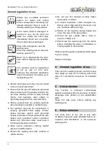
General regulation of use
6
Please use a suitable extraction
system for gases and cutting
fumes. Always wear breathing ap-
paratus whenever there is a risk of
inhaling welding or cutting vapours.
If the mains cable is damaged or
severed in use, do not touch the
cable but unplug the mains plug
immediately. Never use a machine
if the mains cable is damaged.
Keep a fire extinguisher near the
welding area.
Check the welding area for fire after
welding (see UVV
1
)).
Never try to disassemble the pres-
sure reducer. Replace the defective
one.
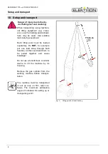
The machine must be transported
or set up only on firm, level
surfaces. The maximum admissible
angle of inclination for setting up or
transporting is 10°.
Service and repair work may only be carried
out by a trained electrician.
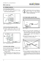
Ensure that the ground cable has good and
direct contact near the welding location. Do
not allow welding current to pass through
chains, ball bearings, steel cables or
grounding equipment; this may melt them.
Secure yourself and the welding machine
when working in elevated or inclined areas.
The machine may only be connected to a
properly grounded mains supply. (Three-
phase four-wire system with grounded
neutral conductor or single phase-three-wire
system with grounded neutral conductor)
socket and extension cable must have a
functional protective conductor.
Wear correct protective clothing, leather
gloves and leather apron.
Protect the welding area with curtains or
mobile screens.
Do not use this machine to thaw frozen
water pipes or cables.
In closed containers, under cramped con-
ditions, and in high electrical risk areas, only
use machines with the S sign.
Switch off the machine during breaks and
close the valve of the gas cylinder.
Secure the gas cylinder with a chain to
prevent it falling over.
Disconnect the mains plug from the mains
before changing the place of installation or
making repairs to the machine.
Please heed the safety regulations which apply
to your country.
Subject to change.
4
General regulation of use
This unit is for welding of steel, aluminium and
their alloys as well as for brazing with CuSi
wires for commercial as well as for industrial
use.
5
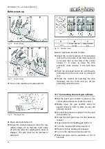
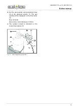
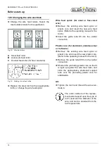
Unit protection
This machine is protected electronically
against overloading. Do not use fuses of higher
amperage than printed on the identification
plate.
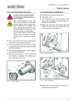
Close the side cover before starting any
welding work.
6
Noise emission
The noise level of the unit is less than
70 dB(A), measured under standard load in ac-
cordance with EN 60974-1 in the maximum
working point.


