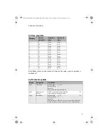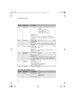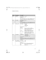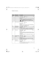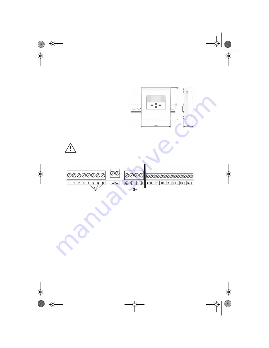
Connection diagram
18
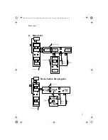
Rail mount
8.
Connection diagram
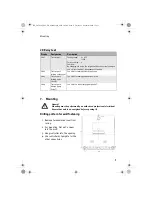
1. Insert mounting feet into rail
mount opening.
2. Lock hook in place by pushing
down.
Hazard!
Connection must be performed by an authorised professional
electrician! Ensure that unit is de-energised before opening it!
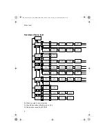
230V connections
Low voltage connections
L=Phase 230V
mains
1=L1 (230V) Pump for mixed heating circuit (
M
K
B
)
2=L1 (230V) Mixing valve O
P
EN
3=L1 (230V) Mixing valve CLOSED
N
=
Neut
ral 230V mains, mixing valve, pumps
Connecti
o
n solar charging pump SOP (isolated), (opt
ion)
=
Earthing
Bus connect
ions for net
w
ork
ing (see paramet
e
r 03:03)
Connections withou
t function
R
C=Connect
ion CET
A
RC, (opt
ion)
F1
=
S
ens
o
r he
at
s
tor
age
ta
nk
Delta-T
(KVT20), (option)
F2=Sens
o
r flow heating circuit
(VF202B)
F3=Sensor heat supplier Delt
a-T (P
T1000
), (option)
F4=
S
ensor outside tempera
ture (AF
2
00)
BA_CETA106_EbV_EN_0450021003_0950-10.book Seite 18 Freitag, 11. Dezember 2009 1:16 13


