background image

41

Instrukcja obs

ł

ugi i monta

ż

u HRD FU-ATEX

www.elektror.pl

PL

9016330 01.20/08

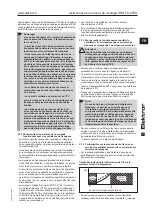
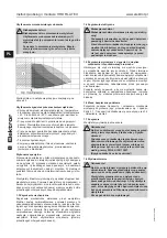
1.9 Temperatura

Ostrze

ż

enie!

Podczas pracy wentylatora jego obudowa silnika/ 

obudowa osi

ą

ga temperatur

ę

 t

ł

oczonego me-

dium. Je

ś

li przekracza ona +50°C, u

ż

ytkownik 

musi zastosowa

ć

 ochron

ę

 przed bezpo

ś

rednim 

dotkni

ę

ciem wentylatora (ryzyko poparzenia!)

Zw

ł

aszcza w przypadku wysokowydajnych typów wentyla-

torów podczas przet

ł

aczania ze strony ssawnej do strony 

wydmuchu mo

ż

e doj

ść

 do wzrostu temperatury t

ł

oczonego 

medium. Tego rodzaju ró

ż

nica temperatur, w zale

ż

no

ś

ci od 

warunków eksploatacji i typu urz

ą

dzenia, mo

ż

e wyst

ę

powa

ć


w zakresie do maks. +20°C.

1.10 Uk

ł

ad ochronny silnika

Ka

ż

dy silnik musi by

ć

 zabezpieczony przed niedopusz-

czalnym nagrzaniem si

ę

 przez urz

ą

dzenie kontrolne lub 

wy

łą

cznik samoczynny silnikowy zgodny z wymaganiami 

dyrektywy ATEX. Urz

ą

dzenia ochronne nadmiarowo-pr

ą

do-

we z zale

ż

nie od pr

ą

du opó

ź

nionym wyzwalaniem musz

ą


nadzorowa

ć

 pr

ą

d znamionowy we wszystkich przewodach 

oraz musz

ą

 by

ć

 w stanie wy

łą

czy

ć

 silnik z zablokowanym 

wirnikiem w przeci

ą

gu czasu wzrostu temperatury t

E

.

Czas wyzwalania urz

ą

dzenia kontrolnego dla krotno

ś

ci pr

ą

-

du rozruchowego I

A

/I

N

 musi by

ć

 krótszy ni

ż

 czas wzrostu 

temperatury tE dla danej klasy temperaturowej.
Czas wyzwalania, pocz

ą

wszy od stanu zimnego przy tem-

peraturze oto20°C podany jest w charakterystyce 

wyzwalania urz

ą

dzenia kontrolnego. Warto

ś

ci czasu wzro-

stu temperatury t

E

 dla poszczególnych klas temperaturo-

wych oraz krotno

ść

 pr

ą

du rozruchowego I

A

/I

N

 podane s

ą

 na 

tabliczce znamionowej lub tabliczce dodatkowej silnika.
W przypadku zespo

ł

ów ATEX z silnikiem Ex eb termiczny 

samoczynny wy

łą

cznik silnikowy z czujnikami termistorowy-

mi do bezpo

ś

redniej kontroli temperatury dopuszczalny jest 

tylko dodatkowo do ochrony nadmiarowej (na zapytanie).
W przypadku zespo

ł

ów do pracy z przemiennikiem cz

ę

stotli-

wo

ś

ci i wyposa

ż

onych w silnik Ex db eb nale

ż

y w tym wzgl

ę

-

dzie koniecznie dodatkowo przestrzega

ć

 wskazówek zawar-

tych w podrozdzia

ł

ach od 3.3.1. do 3.3.4.

1.11 Ha

ł

as

Wskazówka!
Przy dziennej ekspozycji na ha

ł

as na poziomie 80 

dB(A) i/lub szczytowym poziomie ci

ś

nienia akus-

tycznego 135 dB(C) nale

ż

y stosowa

ć

 ochron

ę


s

ł

uchu podczas pracy.

W przeciwnym razie mo

ż

e doj

ść

 do uszkodzenia 

s

ł

uchu.

Poziom ha

ł

asu wytwarzany przez wentylator nie jest jedna-

kowy w ca

ł

ym zakresie wydajno

ś

ci. Emitowany poziom ha

ł

a-

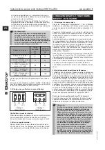
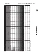
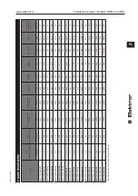
su podany jest w tabeli na stronie 49.
W okre

ś

lonych niekorzystnych przypadkach wymagana jest 

izolacja d

ź

wi

ę

kowa (u

ż

ytkownikowi zaleca si

ę

 przeprowa-

dzenie odpowiednich pomiarów). Izolacja d

ź

wi

ę

kowa musi 

by

ć

 wykonana przez u

ż

ytkownika, aby nie dosz

ł

o do prze-

kroczenia prawnie dopuszczalnych warto

ś

ci maksymalnych 

na stanowiskach pracy w otoczeniu wentylatora.
Jakiegokolwiek rodzaju izolacja d

ź

wi

ę

kowa nie mo

ż

e skut-

kowa

ć

 wzrostem ryzyka wybuchu oraz musi by

ć

 zapewnione 

np. nieprzekroczenie najwy

ż

szej dopuszczalnej temperatury 

otoczenia wynosz

ą

cej +40°C (wentylator).

1.12 Pr

ę

dko

ś

ci obrotowe

Ostrze

ż

enie!

Aby zapobiec obra

ż

eniom cia

ł

a, w 

ż

adnym 

wypadku nie wolno przekracza

ć

 maksymalnej 

pr

ę

dko

ś

ci obrotowej, podanej na tabliczce zna-

mionowej silnika. 
W przypadku przekroczenia maksymalnej pr

ę

d-

ko

ś

ci obrotowej wyst

ę

puje niebezpiecze

ń

stwo 

mechanicznego uszkodzenia wentylatora.

Ka

ż

da cz

ęść

 wentylatora cechuje si

ę

 indywidualn

ą

 cz

ę

stotli-

wo

ś

ci

ą

 w

ł

asn

ą

. Cz

ę

stotliwo

ść

 ta mo

ż

e by

ć

 wzbudzana przez 

okre

ś

lon

ą

 pr

ę

dko

ść

 obrotow

ą

 wentylatora, powoduj

ą

c po-

wstanie zjawiska rezonansu. 
Wentylatory s

ą

 skonstruowane w taki sposób, 

ż

e przy sta

ł

ej 

roboczej pr

ę

dko

ś

ci obrotowej rezonans z regu

ł

y nie wyst

ę

-

puje.
Je

ś

li wentylator pracuje z przemiennikiem cz

ę

stotliwo

ś

ci, w 

niektórych przypadkach mo

ż

e doj

ść

 do wzbudzenia po zmia-

nie pr

ę

dko

ś

ci obrotowej. Do czynników maj

ą

cych wp

ł

yw na 

to zjawisko nale

ż

y równie

ż

 charakterystyczny dla danego 

u

ż

ytkownika sposób monta

ż

u lub pod

łą

czenie instalacji po-

wietrznej.
Je

ś

li cz

ę

stotliwo

ś

ci w

ł

asne le

żą

 w zakresie pr

ę

dko

ś

ci obroto-

wej wentylatora, nale

ż

y je wyeliminowa

ć

, odpowiednio usta-

wiaj

ą

c parametry przemiennika cz

ę

stotliwo

ś

ci.

1.13 Obowi

ą

zki u

ż

ytkownika

U

ż

ytkownik instalacji lub maszyny zobowi

ą

zany jest do eks-

ploatacji maszyny zgodnie z dyrektyw

ą

 99/92/WE (ATEX 

137) oraz w

ł

a

ś

ciwymi przepisami krajowymi; oznacza to np. 

wymóg opisania ryzyka w dokumencie dotycz

ą

cym ochrony 

przeciwwybuchowej.

Ś

rodki, które musz

ą

 by

ć

 podj

ę

te w przypadku zapalenia/

wybuchu lub innego typu awarii:

Je

ś

li w otoczeniu zespo

ł

u lub w jego wn

ę

trzu 

wyst

ą

pi

ł

a de

fl

 agracja, wybuch lub po

ż

ar, to ze-

spó

ł

 nie mo

ż

e by

ć

 dalej u

ż

ywany niezale

ż

nie od 

przyczyny wybuchu. W tym przypadku, jak rów-

nie

ż

 w przypadku innych awarii zespó

ł

 musi by

ć


udost

ę

pniony/przes

ł

any do 

fi

 rmy Elektror celem 

przeprowadzenia dok

ł

adnego badania.

2 INFORMACJE O TRANSPORCIE I 
OBCHODZENIU SI

Ę

 Z MASZYN

Ą

2.1 Transport i obchodzenie si

ę

 z maszyn

ą

•  Przed monta

ż

em i uruchomieniem sprawdzi

ć

 wszystkie 

 cz

ęś

ci pod wzgl

ę

dem wyst

ę

powania uszkodze

ń

 transpor-

  towych. Uszkodzony wentylator mo

ż

e stanowi

ć

 zwi

ę

kszo-

 ne zagro

ż

enie dla bezpiecze

ń

stwa i z tego powodu nie 

 powinien by

ć

 uruchamiany.

•  Nie sk

ł

adowa

ć

 niezabezpieczonego wentylatora na 

  wolnym powietrzu (chroni

ć

 przed wilgoci

ą

).

•  Dobrze przymocowa

ć

 urz

ą

dzenia d

ź

wigowe. U

ż

ywa

ć


 wy

łą

cznie urz

ą

dze

ń

 d

ź

wigowych i chwytaj

ą

cych 

ł

adunek, 

 które posiadaj

ą

 odpowiedni ud

ź

wig. Zabezpieczy

ć

 drogi 

 transportowe.

Summary of Contents for HRD 14T FU

Page 1: ... Betriebs und Montageanleitung Explo sionsgeschützte Ausfüh rung gemäß Richtlinie 2014 34 EU DE Elektror High Pressure Blowers Operating and Assembly Instructions for Explosion protected Model in accordance with Directive 2014 34 EC EN Ventilateurs à haute pression Elektror No tice d instructions et de maintenance Exécution antidéflagrante selon la directive 2014 34 CE FR Wentylatory wysokoci śnie...

Page 2: ...nicht zulässig Die Geräte nach dieser Betriebs und Montageanleitung ent sprechen der auf dem Geräte Leistungsschild angegebenen Kategorie Zündschutzart Temperaturklasse etc Im Folgenden werden die Geräte Kategorien nach ATEX aufgeführt Kategorie 3G Konstruktive Gerätegestaltung zur Vermeidung von Zünd quellen bei Normalbetrieb mit Explosionsgefahr durch Gas G Kategorie 3D Konstruktive Gerätegestal...

Page 3: ...r abzustimmen 1 2 Bestimmungsgemäße Einbaulagen Die Aufstellung der Ventilatoren ist nur im Indoorbereich zugelassen Die Außenaufstellung ist nur mit einem geeigneten Witterungsschutz für den gesamten Ventilator zulässig Stellen Sie sicher dass die Einbausituation das Belüf tungssystem des Antriebsmotors nicht beeinträchtigt Minimaler Abstand Lüfterhaube für Ansaug Kühlluft Antriebsleistung Minima...

Page 4: ...ise im Folgenden 1 4 Elektrische Gefährdungen Gefahr Gefahr durch elektrischen Strom Spannungsführende Bauteile stehen unter Strom und verursachen tödliche Verletzungen Setzen Sie das Gerät vor dem Öffnen Hineinfas sen oder Einführen von Werkzeugen außer Be trieb prüfen die Spannungsfreiheit und sichern es gegen Wiederanlauf 1 5 Gefährdung durch Hineinfassen und unerwarteten Anlauf Durch rotierende...

Page 5: ...rf zu keinerlei Erhöhung des Explosionsrisikos führen und es muss z B sichergestellt sein dass die maximal zulässige Umgebungstemperatur von 40 C Ventilator nicht überschritten wird 1 12 Drehzahlen Warnung Zur Vermeidung von Personenschäden darf die auf dem Motorleistungsschild gestempelte maxi male Drehzahl keinesfalls überschritten werden Bei einer Überschreitung droht die Gefahr einer mechanisc...

Page 6: ...es Motors sind nach dem Schaltbild im Klemmen kasten und nach den einschlägigen örtlichen Bestimmungen vorzunehmen Ausführung der elektrischen Installationen gemäß EN 60079 14 Es ist ein vollständiger Potentialausgleich herzustellen d h ausreichende sach und fachgerechte Erdung aller elektrisch leitenden Teile Überprüfen Sie die Übereinstimmung der Netzspannung mit der Angabe auf dem Leistungsschi...

Page 7: ...r größer der Motorleistung bei max Frequenz Umrichterstrom gleich oder größer Motorbemessungs strom bei max Frequenz Ausgangsspannung des Umrichters gleich der Motorbe messungsspannung bei max Frequenz Versorgungsspannung max 480V inklusive 5 Spannungstoleranz Pulsfrequenz des Umrichters gleich oder größer 8 kHz da eine geringere Pulsfrequenz starke Motorgeräusche erzeugen kann Hinweis Sofern ein ...

Page 8: ...f dem Leistungsschild angegeben ist da entweder der Motor überlas tet wird oder durch die überhöhte Drehzahl der Ventilator zerstört werden kann Es darf ebenfalls am Umrichter kein sogenannter Boost eingestellt werden da eine übermäßig starke Erwärmung des Antriebsmotors die Folge wäre Die Tempe raturfühler sind zum Schutz des Antriebsmotors an den entsprechenden Umrichtereingängen anzuschließen D...

Page 9: ...ie Betriebsstörungen durchgeführte Maßnahmen sowie die Einhaltung aller geltenden Vorschriften und der Hersteller angaben zu dokumentieren Es ist empfehlenswert diese Dokumentation in einem Betriebsbuch vorzunehmen und dieses sicher zu verwahren 5 3 Kugellager Gefahr Verletzungs und Sachschadengefahr durch un sachgemäße Handhabung Das Verletzungs und Sachschadenrisiko erhöht sich deutlich durch fa...

Page 10: ...ilators unseren Service E Mail service elektror de Tel 49 711 31973 2222 Fax 49 711 31973 52222 Sie erhalten von uns eine kompetente Analyse des techni schen Zustandes inklusive einer Empfehlung über die am Besten geeignete Vorgehensweise Dazu liefern wir Ihnen Informationen wie das Produkt in einen optimalen Zustand zurückversetzt werden kann Sollte ein Weiterbetrieb oder eine Reparatur nicht emp...

Page 11: ...insbesondere auch für besondere Verwendungen und Einsatzbedingungen die nicht ausdrücklich mit der Fa Elektror abgestimmt wurden Elektror lehnt zudem jede Haftung ab für Veränderungen oder Umbauten am gelieferten Gerät oder Zubehör und ins besondere dann wenn diese Veränderungen den Explosi onsschutz beeinträchtigen können Ebenso haftet die Fa Elektror nicht für unsachgemäße ver spätete nicht durc...

Page 12: ... Maschine eingebaut werden soll den Bestimmungen der Maschinenrichtlinie 2006 42 EG entspricht Die folgenden harmonisierten Normen wurden angewandt DIN EN ISO 12100 2011 Sicherheit von Maschinen Allgemeine Gestaltungsleitsätze Risikobeurteilung und Risikominderung ISO 14694 2003 Industrieventilatoren Technische Vorschriften für die Wuchtgüte und Vibrationspegel DIN EN 1127 1 2019 Explosionsfähige ...

Page 13: ...9 0 98 HRD 16T FU 105 2 2 2 5 20 0 6100 6040 400 105 4 7 2 20 45 0 96 HRD 16T FU 105 3 0 2 5 35 0 6100 5928 400 105 8 0 3 00 48 0 93 HRD 2T FU 95 2 2 2 5 13 5 8500 5466 400 95 4 55 2 20 55 0 87 HRD 2T FU 95 3 0 2 5 27 0 8500 5364 400 95 7 3 3 00 62 0 87 HRD 60 FU 105 4 0 5 0 14 0 10500 6105 400 105 11 5 4 00 61 0 93 HRD 60 FU 105 5 5 5 0 25 0 10500 6090 400 105 11 2 5 50 78 0 93 HRD 60 FU 105 7 5 ...

Page 14: ...ble The units described in these operating and assembly instruc tions correspond to the category type of ignition protection temperature class etc specified on the nameplate The following section lists the unit categories according to ATEX Category 3G The equipment is so designed and constructed as to prevent ignition sources during normal operation in areas where an explosion hazard due to gases ...

Page 15: ... 09 Secure the fan flange base and console so that they lie flat The following installation positions are permitted for the fans Installation position with a horizontal motor shaft with base with console Up to and including no restriction Temperature and ambient conditions max temperature min temperature Flow medium temperature at the intake 40 C 20 C Ambient tempera ture 40 C 20 C Avoid aggressiv...

Page 16: ...insert ing tools into the appliance always shut it down and wait until all moving parts come to a standstill Make sure the ap pliance is reliably protected against restarting while work is in progress Also make sure that no hazardous situation can occur as a consequence of restarting after shutdown e g as a result of a power cut or blockage 1 6 Weight and stability Beware of falling hazards during...

Page 17: ...ower is operated on a frequency converter These circumstances are also influenced by the customer s individual installation situation or ventilation con nection These natural frequencies must be excluded by parametris ing the frequency converter accordingly should they be pre sent within the speed range of the blower 1 13 Obligations of the owner The owner of an installation or machine is required...

Page 18: ...ing plate Minimum frequency 50 Hz 5 Hz 60 Hz 5 Hz 60 Hz 35 Hz A direct evaluation of the PTC resistor sensor by the fre quency converter is not usually permissible in ATEX applica tions in this regard please refer to the specifications of the converter manufacturer Note For operation of the drive motor with a frequency converter the following points should also be noted Only motors marked Ex db eb...

Page 19: ...e motor with converter operation The limit data for converter operation is stamped on the nameplate of the motors with pressure proof encapsulation At the converter the voltage frequency assignment must be set according to the diagram UB 0 fB Prohibited range Prohibited UB und fB see nameplate Never set a higher frequency speed at the converter than the max frequency fB indicated on the nameplate ...

Page 20: ...st frequency converters are designed to operate on indus trial grids If the converter is connected directly to and oper ated on a public grid then additional interference suppres sion measures such as a mains choke must be built into the mains feeder For further information refer to the converter manufacturer s specifications 5 INSTRUCTIONS FOR MAINTENANCE 5 1 Basic information Before and after ma...

Page 21: ...erwise manipulated The equipotential bonding must be inspected in conjunction with every maintenance job and shall be in good operating order after the maintenance job is completed The measures must not lead to interconnections between explosion protec tion zones The radial shaft seals must be in perfect condition this must be checked during all maintenance work 5 5 Micro filters The degree of clo...

Page 22: ...e and inadmissible material com binations have been published Inadmissible material com binations may render ineffective any constructive measures aimed at achieving explosion protection This may substan tially increase the explosion risk entailed in ATEX products Spare parts list of non explosion protected devices must not be applied to ATEX appliances and are therefore void Recommendation Use onl...

Page 23: ...lly completed machine is not permitted until it has been verified that the machine in which the partially completed machine is to be installed complies with the provisions of the Machinery Directive 2006 42 EC The following harmonised standards have been applied DIN EN ISO 12100 2011 Safety of machinery General principles for design Risk assessment and risk reduction ISO 14694 2003 Industrial fans...

Page 24: ...00 5940 400 105 4 1 1 50 39 0 98 HRD 16T FU 105 2 2 2 5 20 0 6100 6040 400 105 4 7 2 20 45 0 96 HRD 16T FU 105 3 0 2 5 35 0 6100 5928 400 105 8 0 3 00 48 0 93 HRD 2T FU 95 2 2 2 5 13 5 8500 5466 400 95 4 55 2 20 55 0 87 HRD 2T FU 95 3 0 2 5 27 0 8500 5364 400 95 7 3 3 00 62 0 87 HRD 60 FU 105 4 0 5 0 14 0 10500 6105 400 105 11 5 4 00 61 0 93 HRD 60 FU 105 5 5 5 0 25 0 10500 6090 400 105 11 2 5 50 ...

Page 25: ...plate and blower type rating plate Gehäusestellungen Die Gehäusestellung des Ventilators ist für die Bestellung einiger Ersatztei le entscheidend Bestellen Sie Ersatzteile zur Drehrichtung passend Housing positions The position of the blower housing is important for ordering several spare parts Order spare parts which match the direction of rotation RD 0 Fl RD 270 El RD 90 Gl RD 180 Hl LG 0 Br LG ...

Page 26: ...cette directive est en vigueur ou reconnue juri diquement sans restrictions Il n est pas permis de transformer ni de modifier le ventilateur mis en circulation Les appareils correspondant aux présentes instructions de service et de montage répondent à la catégorie au mode de protection à la classe de température etc mentionnés sur la plaque signalétique de l appareil Ci après figurent les catégori...

Page 27: ...société Elektror avec laquelle elles seront adaptées 1 2 Positions d installation conformes L installation des ventilateurs est autorisée uniquement en intérieur L installation extérieure n est autorisée qu avec une protection contre les intempéries adaptée pour l ensemble du ventilateur Assurez vous que les conditions d installation n affectent pas les performances du système de ventilation du mot...

Page 28: ... de protection de la santé Afin d exclure les risques résiduels de manutention nous recommandons d utiliser le cas échéant de porter un équi pement de sécurité approprié pendant toutes les phases de vie de l appareil respecter les consignes suivantes 1 4 Risques d ordre électrique Danger Risque associé au courant électrique Les composants conducteurs de courant sont sous tension et provoquent des ...

Page 29: ...xploitant d effectuer les mesures La protection contre le bruit sera effectuée par l exploitant dans le but de ne pas dépasser dans le périmètre du ventilateur les seuils admis par la réglementation sur les lieux de travail La protection contre le bruit de quelque type que ce soit ne doit en aucun cas conduire à une augmentation du risque d explosion il faut s assurer par exemple que la tempéra ture...

Page 30: ...t ne pas exposer à des vibrations ni à des chocs Couvrir les piquages d aspiration ou de refoulement ouverts par des grilles de protection conformes à la norme EN ISO 13857 Mesure au niveau du flasque de bride si possible près du roulement Point de mesure La direction de mesure Vitesse d oscillation maximale admissible valeurs limites conformément à la norme ISO 14694 2003 E catégorie BV 3 Montage...

Page 31: ...ur remplit les exigences de sécurité et qu une remise à zéro ne peut s effectuer que manuellement Les moteurs utilisés Ex db eb II 2GD T4 135 C sont mu nis de thermistances CTP pour protection intrinsèque Celles ci doivent être branchées à un appareil de déclen chement certifié ATEX et analysées afin que le ventilateur soit arrêté de manière fiable en cas d erreur voir 3 3 1 L appareil de surveilla...

Page 32: ...ystème de protec tion déclenchement du disjoncteur protecteur réaction de l évaluateur CTP sur les moteurs à thermistance CTP ou in terruption produite par le système de protection du variateur de fréquence dans les applications ATEX avec variateurs de fréquence par ex il faut effectuer une nouvelle mise en marche de l appareil après que la cause de la défaillance a été identifiée et éliminée Dans ...

Page 33: ...enance ainsi que la mainte nance elle même et la remise en état En plus des instruc tions de service de l appareil concerné de la réglementation et des recommandations pour l ensemble de l installation il faut respecter les points suivants 5 2 Périodicité des révisions et de l entretien L exploitant doit définir lui même la périodicité du nettoyage de l inspection et de la maintenance en fonction ...

Page 34: ...un outil de démontage approprié Pour ce faire le moyeu du rotor dispose de rai nures ou d un filet Pendant la pose du rotor sur l arbre des coups ou des chocs doivent être évités 5 7 Moteurs ATEX Les moteurs ATEX ne peuvent être remplacés comme unité complète Conformément à la norme EN ISO 60079 la répa ration des moteurs ATEX utilisés sera exclusivement réali sée par le fabricant du moteur Après ...

Page 35: ...ne s appliquent pas aux appareils ATEX et par conséquent ne sont pas valables Recommandation La mise en oeuvre des pièces de re change d origine de la Sté Elektror vous permet de réduire le risque le plus possible 6 INFORMATIONS RELATIVES A LA SECURITE LORS DE LA MISE HORS SERVICE ET DU DEMONTAGE La déconnexion de tous les raccordements électriques et toutes les opérations électrotechniques supplé...

Page 36: ...ne incomplète est interdite jusqu à ce qu il soit constaté que la machine dans laquelle doit être intégrée la machine incomplète répond aux dispositions de la Directive Machines 2006 42 CE Les normes harmonisées suivantes ont été appliquées DIN EN ISO 12100 2011 Sécurité des machines Principes généraux de conception Appréciation du risque et réduction du risque ISO 14694 2003 Ventilateurs industri...

Page 37: ... 1 5 2 5 7 0 6100 5940 400 105 4 1 1 50 39 0 98 HRD 16T FU 105 2 2 2 5 20 0 6100 6040 400 105 4 7 2 20 45 0 96 HRD 16T FU 105 3 0 2 5 35 0 6100 5928 400 105 8 0 3 00 48 0 93 HRD 2T FU 95 2 2 2 5 13 5 8500 5466 400 95 4 55 2 20 55 0 87 HRD 2T FU 95 3 0 2 5 27 0 8500 5364 400 95 7 3 3 00 62 0 87 HRD 60 FU 105 4 0 5 0 14 0 10500 6105 400 105 11 5 4 00 61 0 93 HRD 60 FU 105 5 5 5 0 25 0 10500 6090 400...

Page 38: ...rych obowiązuje ta dyrektywa lub uznana jest prawnie bez ograniczeń Przebudowa lub zmiany w wentylatorze wprowadzonym do obiegu są niedozwolone Urządzenia których dotyczy niniejsza instrukcji obsługi i montażu odpowiadają parametrom podanym na tabliczce znamionowej urządzenia tj kategorii typowi ochrony prze ciwwybuchowej klasie temperaturowej itd Poniżej przedstawiono kategorie urządzeń według dy...

Page 39: ...czeniem Ustawianie wentylatorów jest dozwolone tylko w pomiesz czeniach Instalacja na zewnątrz jest dozwolona tylko przy odpowiedniej ochronie pogodowej całego wentylatora Upewnić się że sytuacja montażowa nie wpływa nieko rzystnie na system wentylacji silnika napędowego Minimalny odstęp obudowy wentylatora dla wlotu zim nego powietrza Moc napędowa Minimalny odstęp od obudowy wentylatora mm cale 1...

Page 40: ...lecamy stosowanie względnie noszenie odpowiedniego wyposażenia ochronnego we wszystkich fazach użytkowania urządzenia prosimy przestrzegać niżej podanych zasad 1 4 Zagrożenia elektryczne Niebezpieczeństwo Niebezpieczeństwo stwarzane przez prąd elektry czny Podzespoły przewodzące prąd są pod napięciem i powodują śmiertelne obrażenia Przed otwarciem urządzenia sięgnięciem do jego wnętrza lub włożeni...

Page 41: ...iarów Izolacja dźwiękowa musi być wykonana przez użytkownika aby nie doszło do prze kroczenia prawnie dopuszczalnych wartości maksymalnych na stanowiskach pracy w otoczeniu wentylatora Jakiegokolwiek rodzaju izolacja dźwiękowa nie może skut kować wzrostem ryzyka wybuchu oraz musi być zapewnione np nieprzekroczenie najwyższej dopuszczalnej temperatury otoczenia wynoszącej 40 C wentylator 1 12 Prędk...

Page 42: ...zej eksploatacji wentylatora nie narażać go na drgania wstrząsy i uderzenia Otwarte króćce wlotowe i wylotowe osłonić kratkami ochronnymi według normy DIN EN ISO 13857 Pomiar na osłonie łożyska kołnierza jeśli to możliwe w pobliżu łożyska Punkt pomiarowy Kierunek pomiaru Maksymalnie dopuszczalna prędkość drgań Wartości graniczne zgodnie z ISO 14694 2003 E kategoria BV 3 Zamontowane na sztywno mm s...

Page 43: ...lub gwiazdowym w zależności od napięcia wejściowego przemiennika Miarodajne są dane umieszczone na tabliczce znamionowej silnika Informacje na temat instalacji zgodnej z zasadami kompa tybilności elektromagnetycznej i montażu falownika poda ne są w dokumentacji dostawcy Odpowiednie są przekaźniki załączające spełniające kry teria dyrektywy IEC 61508 które w przypadku zakłócenia mogą niezawodnie pr...

Page 44: ...ć wskazówek zawartych w podrozdziale 1 1 dotyczących użytkowania maszyny zgodnie z jej prze znaczeniem oraz zasad bezpieczeństwa opisanych w pod rozdziałach od 1 2 do 1 13 Jeśli podczas pracy zostanie przekroczony prąd znamiono wy silnika napędowego należy sprawdzić czy wartość na pięcia sieciowego i częstotliwości sieciowej odpowiada para metrom urządzenia tabliczka znamionowa silnika Po wyłączen...

Page 45: ...ich jak temperatura itp Należy zapewnić dostęp ułatwiający przeprowadzanie regu larnych konserwacji Czynności zaradcze przegląd i obsługę techniczną może wykonywać tylko dostatecznie wykwalifikowany i regularnie szkolony personel techniczny Oprócz instrukcji obsługi da nego urządzenia oraz instrukcji i zaleceń dla całej instalacji należy przestrzegać następujących zasad 5 2 Częstotliwość przeglądó...

Page 46: ...użytkownik musi zapewnić przepustowość filtrów 5 6 Wirnik ATEX Wyważenie oraz bicie czołowe i promieniowe wirnika nie może pogorszyć się wskutek przeprowadzenia konserwacji naprawy lub wymiany części Wirnik należy wymienić najpóźniej w przypadku wystąpienia wyraźnie dających się stwierdzić wibracji drgań lub wyraź nego rozpoznawalnego mechanicznego starcia lub uszko dzeń Do ściągnięcia wirnika uży...

Page 47: ...kazy części zamiennych do urządzeń nie posiadających wykonania przeciwwybuchowego nie mają zastosowania do urządzeń ATEX i z tego względu są w tym zakresie nieważ ne Zalecenie Użycie oryginalnych części zamiennych firmy Elektror ułatwia zastosowanie sposobu postępowania o ni skim stopniu ryzyka 6 INFORMACJE ZWIĄZANE Z BEZPIE CZEŃSTWEM DOTYCZĄCE WYŁĄCZE NIA Z EKSPLOATACJI I DEMONTAŻU Odłączenie wsz...

Page 48: ...kończona spełnia postanowienia dyrektywy maszynowej 2006 42 WE Zastosowano następujące normy zharmonizowane DIN EN ISO 12100 2011 Bezpieczeństwo maszyn Pojęcia podstawowe ogólne zasady projektowani analiza ryzyka i redukcja ryzyka ISO 14694 2003 Wentylatory przemysłowe Przepisy techniczne dotyczące jakości wyrównoważenia i poziomu drgań DIN EN 1127 1 2019 Atmosfery wybuchowe Zapobieganie wybuchowi...

Page 49: ...00 5940 400 105 4 1 1 50 39 0 98 HRD 16T FU 105 2 2 2 5 20 0 6100 6040 400 105 4 7 2 20 45 0 96 HRD 16T FU 105 3 0 2 5 35 0 6100 5928 400 105 8 0 3 00 48 0 93 HRD 2T FU 95 2 2 2 5 13 5 8500 5466 400 95 4 55 2 20 55 0 87 HRD 2T FU 95 3 0 2 5 27 0 8500 5364 400 95 7 3 3 00 62 0 87 HRD 60 FU 105 4 0 5 0 14 0 10500 6105 400 105 11 5 4 00 61 0 93 HRD 60 FU 105 5 5 5 0 25 0 10500 6090 400 105 11 2 5 50 ...

Page 50: ...znamionowa Positions du boîtier Il est essentiel d indiquer la position du boîtier du ventilateur à la comman de de certaines pièce de rechange Les pièces de rechange commandées doivent correspondre au sens de rotation Położenia obudowy Położenie obudowy wentylatora ma decydujące znaczenie przy zamawianiu niektórych części zamiennych Części zamienne należy zamawiać odpo wiednio do kierunku obrotów...

Page 51: ...51 Instrukcja obsługi i montażu HRD FU ATEX www elektror pl PL 9016330 01 20 08 ...

Page 52: ...roduktmanagement unter der Rufnummer 49 711 31973 1111 zur Verfügung You will find further information about our products on the internet at www elektror com Our Product management will be pleased to answer your queries at 49 711 31973 1111 Pour de plus amples informations sur nos produits consulter www elektror fr Notre Management de produits au numéro 49 711 31973 1111 répondra volontiers à vos ...

Reviews: