- 70 -
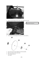
10
11
12
13
14
15
16
screw
nut
Washer
Locking nut
Screw
Washer
Spring washer
M5x15
M6
Ø5
M5
M5X12
Ø5
Ø5
1
1
1
1
2
2
2
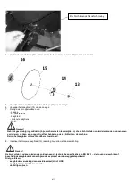
5. Procedure 5
1
Locking knob
1
2
Locking knob
1
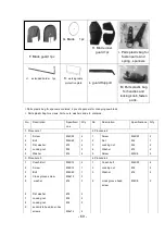
Remark: All the fasten parts and spare parts are listed in the table will be used for assembly as the following detail
“Machine installation” procedures.
3 Mains connection
Danger! High voltage
Operate the machine only on a power source matching the following requirements
(see also “Technical specifications”):
-
Outlets with neutral wire, being properly installed, earthed and tested.
-
Mains voltage and frequency must conform with the date stated on the machine’s nameplate.
-
Fuse protection by a residual current device (RCD) of 30 mA fault current sensitivity.
-
System impedance Z
max.
at the interconnection point (house service connection) 0.35 Ohm maximum.
Note:
Check with your local Electricity Board or electrician if in doubt whether your house service connection
meets these requirements.
Position power supply cable so it does not interfere with the work and is not damaged.
Protect power supply cable from heat, aggressive liquids and sharp edges.
Use only rubber-jacked cable of sufficient lead cross section as extension cable.
Do not pull on power supply cable to unplug.
Summary of Contents for 5411074158590
Page 13: ...13 SCH MA DES BRANCHEMENTS...
Page 41: ...41 AANSLUITSCHEMA...
Page 66: ...66 WIRING DIAGRAM...
Page 72: ...72 Procedure 2 1 loosen coach bolt flat washer and locking nut on spring guide tube...
Page 87: ...87...


