- 74 -
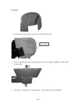
Procedure 3
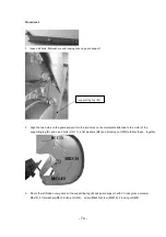
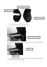
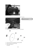
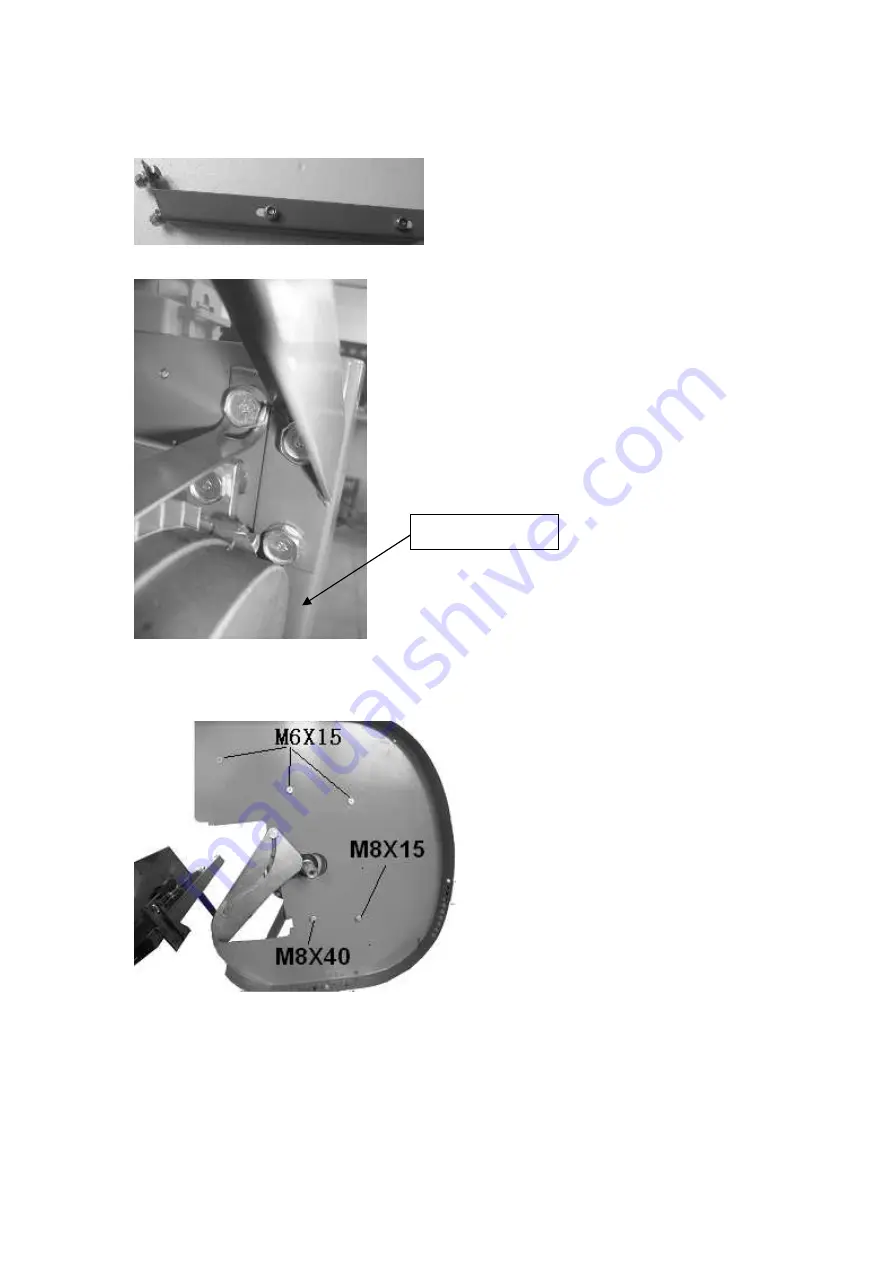
1. loosen all bolts ,flat washers and locking nuts on guard support .
2. Align the two holes on the guard support into the two holes on the metal plate attached to the motor of the
supporting leg (B), and use 2 bolts (
M8X15
), 4 flat washers (Ø8) and 2 locking nut (M8) to fasten these together,
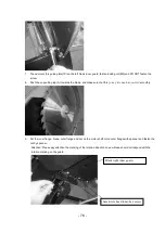
3. Mount the left blade outer guard on the supporting leg (B) and guard support, with 3 Cross groove screws(
M6x15), 3 flat washers(Ø6),3 locking nut(M6), screw (M8x40),screw (M8X15), 2 locking nut(M8)
supporting leg (B)
Summary of Contents for 5411074158590
Page 13: ...13 SCH MA DES BRANCHEMENTS...
Page 41: ...41 AANSLUITSCHEMA...
Page 66: ...66 WIRING DIAGRAM...
Page 72: ...72 Procedure 2 1 loosen coach bolt flat washer and locking nut on spring guide tube...
Page 87: ...87...


