5
USER INFORMATION
Remote control electronic ignition
system RCE GV60
The appliance is supplied with a remote control.
Ignition, controlling the flame height and switch
-
ing off are performed by the remote control that
operates a receiver in the control hatch. For
some appliances, no control hatch is supplied.
In that case, the receiver is placed under the
appliance. The receiver and remote control are
battery powered. The receiver requires 4
penlite (AA type) batteries, the remote control
requires a 9V block battery. At normal use, the
batteries will have an average life of one year.
You can also use an optional adapter. Ask your
installer for information. In that case you will
need a 230 V connection near your appliance.
- temperature display in degrees Celsius or
Fahrenheit;
- time;
- thermostat function;
- timer for thermostat function.
Setting the communication code
Prior to putting the application into operation, a
communication code must be set between the
remote control and the receiver. The code is cho-
sen randomly from the 65000 available codes.
As a result, the chance that other remote controls
near you are using the same code and affect the
operation of your appliance is very small.
Follow the procedure described below:
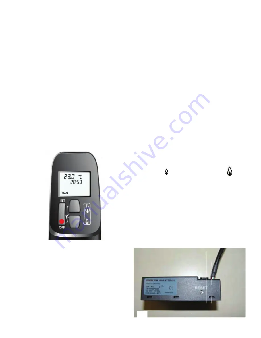
Hold down the reset button on the receiver,
until you hear two consecutive sound signals
(see fig. 2). After the second, longer signal,
let go of the reset button.
Press button (small flame) or button
( large flame) on the remote control within 20
seconds, until you hear an extra long sound
signal: this is the confirmation of a correct
communication.
!Caution When installing a new remote con
-
trol or receiver, you must set a new commu
-
nication code.
The appliance’s standard functions such as
ignition, controlling the flame
height, standby (pilot burner) position and
switching off are performed in the
MAN position, the manual control of the
remote control (see fig. 2).
In addition, the remote control can also be
used to set a number of additional
functions:
1
2
Summary of Contents for Bidore
Page 15: ...15 installer information ...
Page 16: ...16 installer information ...
Page 17: ...17 installer information ...
Page 18: ...18 installer information ...
Page 34: ...34 Technical drawings techniCAL INFORMATION Trisore 95 Bidore 95 ...
Page 35: ...35 technical information Bidore 70 Trisore 70 ...
Page 40: ...40 Element4 B V Paxtonstraat 23 8013 RP Zwolle The Netherlands ...


