background image

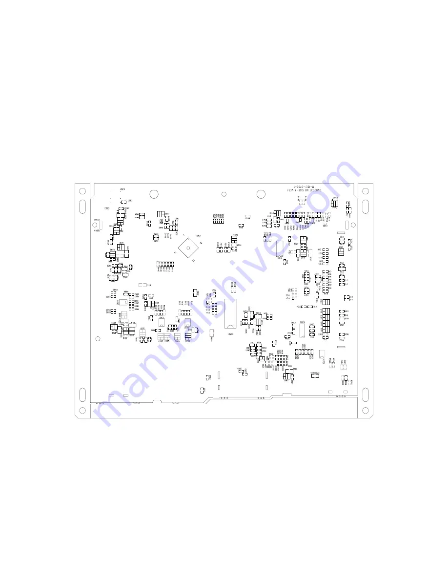
7-4

7-4

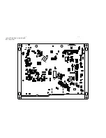
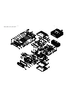
LAYOUT DIAGRAM - MAIN BOARD
BOTTOM VIEW

Summary of Contents for MX-390DVD

Page 1: ...Safety Instruction etc 1 4 to 1 5 Preparations Controls 1 6 to 1 8 Maintenance Troubleshooting 1 9 Disassembly Instructions Service positions 2 Set Block diagram 3 Set Wiring diagram 4 Key Board 5 Servo Board 6 Main Board 7 Set Mechanical Exploded view parts list 8 MX 390DVD UNE P R U G N R K E T D ...

Page 2: ...ications and design are subject to change without notice for product improvements Continuous power output 20Wx4 channels 4 10 T H D Remote control 1 Disc Player System Frequency response Signal noise ratio Total harmonic distortion Channel separation Disc digital audio system 20 Hz 20KHz 80 dB Less than 0 20 1KHz 60 dB FM Stereo Radio Frequency range Sensitivity Frequency response Stereo separatio...

Page 3: ...ltmeter e g PM5326 250Hz 15kHz e g 7122 707 48001 e g PM2534 S N and distortion meter e g Sound Technology ST1700B Ri 50 Frame aerial e g 7122 707 89001 To avoid atmospheric interference all AM measurements have to be carried out in a Faraday s cage Use a bandpass filter or at least a high pass filter with 250Hz to eliminate hum 50Hz 100Hz DUT L R LEVEL METER e g Sennheiser UPM550 with FF filter S...

Page 4: ...N SOLDER WICK 4822 321 40042 e g A PAIR OF TWEEZERS HEATING HEATING SOLDERING IRON SOLDER WICK CLEANING PRECAUTIONS COPPER TRACK IRON CORRECT SOLDERING IRON SOLDERING CHIP COMPONENT EXAMPLES CORRECT IRON SOLDERING NO e g A PAIR OF TWEEZERS SLODERING IRON SLODER SLODERING TIME SLODERING IRON 0 5 0 8mm 3 secretary side PRESSURE PRESSURE SOLDER 0 5 0 8mm A B C B A HANDLING CHIP COMPONENTS ...

Page 5: ...fde potentiaal AVVERTIMENTO Tutti IC eparecchi semi conduttori sono sensibili alle scariche statiche ESD La loro longevita potrebbeessere fortemente ridatta in caso di non osservazione della piu grande cauzione alla loro manipolazione Durante le riparazioni occorrequindi essere collegato allo stesso potenziale che quello della massa dell apparecchio tramite unbraccialetto a resistenza Assicurarsi ...

Page 6: ...elay control Lead Amplifier relay control Lead ISO Connector Connector Original wiring Modified wiring Red Yellow Yellow Red Red Yellow Yellow Red Antenna Fuse 15A R Red L White Yellow Line out Gray Amplifier For some VW Audi or Opel Vauxhall car models you may need to modify wiring of the supplied power cord as illustrated or else the memory of the unit may be lost after you power off Contact you...

Page 7: ...er ON OFF OIRT FM1 FM2 FM3 Radio preset scan Radio auto preset AMS Tuner Disc play when disc is in band switch Radio tune INT RPT RDM 4X45W PUSH SEL MENU VOL VOL MON SRC LOUD 1 2 3 4 5 6 LO DX BAND DSP AMS Radio local distant Display switch MENU IR CAR DVD PLAYER MX 390DVD Remote Sensor FM stereo mono To fastsearch within a track skip tonext or previous track Loudness P N R L Video System PAL NTSC...

Page 8: ... battery to give off heat crack or start a fire When throwing away or saving the battery wrap it in tape and insulate otherwise the battery may start to give off heat crack or start a fire Do not poke the battery with tweezers or similar tools Doing this may cause the battery to give off heat crack or start a fire Power On Off Press to turn on off the unit 1 ABC 2 DEF 3 GHI 4 JKL 5 MNO 7 TUV 8 WXY...

Page 9: ... of higher signal level Much noise in broadcasts Preset station is reset Battery cable is not correctly connected Connect the battery cable to the terminal that is always live Error Display Messages Disc is not CD or contains no MP3 files Disc upside down Recovery error check the disc MP3 error check the disc Disc is upside down Place disc in the correct direction and the label side up Disc is dir...

Page 10: ...move 2 pcs screw from front cabinet Remove 2 pcs screw from metal side Remove the screw on the left side of the cabinet Loosen 8 screws to remove heatsink top cover bottom cover Remove the 2 pcs screw to dismantle the frame Remove 6 pcs screw on the main board Pull out FPC wire Remove the connector from the mainboard Remove the 2 pcs screw to dismantle the frame Remove the screw on the right side ...

Page 11: ...2 2 DISMANTLING INSTRUCTIONS 2 2 Service Position A Service Position B Service Position C Service Position D ...

Page 12: ...r Supply DVD 9V D V D 5 V AP1507 DC 11 16V Ground D9V B5V D 9 V G N D MCU DC 5V MCU DC 5V ACC DC 11 16V Controlled Power ACC SDRAM M Motor Driver AM5668 SPHE8202D VIDEO OUT MIC ROM TSOP48PIN Analog Audio I P M MIC FLASH MX29LV800T DVD R DVD L DVD PLAYER 4 IN 1 SINGLE CHIP 1MX16X4BANK TSOP1154PIN Pre Amp RC4558 Sub Out AUX IN AUX R AUX L L R CD L CD R Tuner Module CET 7000 Tuner R Tuner L A M F M I...

Page 13: ...4 4 SET WIRING DIAGRAM ...

Page 14: ...5 1 5 1 LCD PIN CONNECTION KEY BOARD PIN SEGMENT DISPLAY TABLE OF CONTENTS LCD Display 5 1 Circuit Diagram 5 2 Layout Diagram 5 3 Electrical Parts List 5 4 ...

Page 15: ...5 2 5 2 CIRCUIT DIAGRAM KEY BOARD ...

Page 16: ...5 3 5 3 LAYOUT DIAGRAM KEY BOARD TOP VIEW LAYOUT DIAGRAM KEY BOARD BOTTOM VIEW ...

Page 17: ... 5 1 10W 0805 RES 47KΩ 5 1 16W 0603 RES 750Ω 5 1 10W 0805 RES 1K2Ω 5 1 16W 0603 RES 1K8Ω 5 1 16W 0603 RES 2K7Ω 5 1 16W 0603 RES 3K9Ω 5 1 16W 0603 RES 5K6Ω 5 1 16W 0603 RES 1KΩ 5 1 16W 0603 RES 1K5Ω 5 1 16W 0603 RES 2K2Ω 5 1 16W 0603 RES 8K2Ω 5 1 16W 0603 RES 470Ω 5 1 10W 0805 CAP 0805 105 50V Y5V 80 20 CAP 1nF 10 16V X7R 0603 TACT SW KPS 1107YB 130 o 14PIN 2 0mm SOCKET MALE ESTF2 14 01 90 ENCODER ...

Page 18: ...6 1 6 1 SERVO BOARD TABLE OF CONTENTS Circuit Diagram 6 2 Layout Diagram 6 3 Electrical Parts List 6 4 ...

Page 19: ...6 2 6 2 CIRCUIT DIAGRAM SERVO BOARD ...

Page 20: ...6 3 6 3 CIRCUIT DIAGRAM SERVO BOARD ...

Page 21: ...6 4 6 4 CIRCUIT DIAGRAM SERVO BOARD ...

Page 22: ...6 3 6 3 LAYOUT DIAGRAM SERVO BOARD TOP VIEW LAYOUT DIAGRAM SERVO BOARD BOTTOM VIEW ...

Page 23: ...21803010331 121803000470 121803000472 121803000473 121803000681 121803000683 121803000821 121845090107 122000000179 122040000011 122040000061 122040000042 142206000020 142251000001 142245000048 142251000005 142400000635 142400000416 142400000108 142400000504 142400000505 142400000179 142410000024 142410000108 123800000018 133010000355 121604000562 121803000272 121604000473 142245000015 12160400043...

Page 24: ...7 1 7 1 MAIN BOARD TABLE OF CONTENTS Circuit Diagram 7 2 Layout Diagram 7 3 to 7 4 Electrical Parts List 7 5 to 7 6 ...

Page 25: ...7 2 7 2 CIRCUIT DIAGRAM MAIN BOARD ...

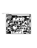
Page 26: ...7 3 7 3 LAYOUT DIAGRAM MAIN BOARD TOP VIEW ...

Page 27: ...7 4 7 4 LAYOUT DIAGRAM MAIN BOARD BOTTOM VIEW ...

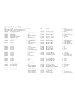
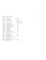
Page 28: ... R807 R808 R438 R821 R439 R809 R102 R111 R103 R129 R425 R128 R441 R533 121604000104 121604010105 121604000154 121604000181 121604000222 121604000224 121604000274 121604000331 121604000332 121604000472 121604000473 121604000562 121604000752 121604000823 121606000000 121606000010 121606000100 121606000102 121606000222 121606000331 121606000471 121803000101 121803000102 121803000103 121803000104 1216...

Page 29: ... IC LC72130 DIP24S SANYO IC TDA7384 FLEXIWATT25 ST IC KIA7027 TO 92 KEC REC DIODE 1N5822 3A 0 9V 40V DO 27 CRYSTAL 4 500MHZ 30PPm 30 80 HC 49 US DIP 30PF CRYSTAL 8 000MHZ 30PPm 20 70 HC 49 US DIP 18PF CRYSTAL 32 768MHz 20ppm 20 70 CL 12 5pF TUning Fork TUNER CET 702CFYA FM OIRT 6PIN 2 0mm WAFER DIP 180 14PIN 2 0mm WAFER 90 CM700 20PIN PWR SPK EST KNT 20 04 CONNECTOR 20PIN 1 0mm CONNECTOR FZC6A 020...

Page 30: ...8 1 8 1 EXPLODED VIEW MAIN UNIT ...

Page 31: ...CAD310 BRACKET FRONT U CD SECC T1 0 NUT White Znic M3X2 5 SCREW BM White Ni M3X8 SCREW PA White Ni M2 6X8 CMU706 BRACKET DECK FRONT OF CLC01 SECC T1 0 SB ASSM DVD PLAYER DL 30H Foryou Pivot screw M2 6 19 CM701 TOPCOVER SECC T0 6 DVD703S BRACKET REAR DECK SECC 1 0mm SCREW BTS White Znic M2 6X3 CMV100 POLE CMV100 RUBBER SCREW BTS White Ni M2 6X14 CAD310 SHORT SHEET SECC T0 6 ANTENNA W GROUND 230mm S...

Reviews: