background image

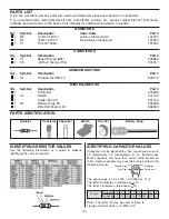
PARTS LIST

If you are a student, and any parts are missing or damaged, please see instructor or bookstore.
If you purchased this metal detector kit from a distributor, catalog, etc., please contact Elenco

TM

Electronics

(address/phone/e-mail is at the back of this manual) for additional assistance, if needed.

RESISTORS

Qty.

Symbol

Description

Color Code

Part #

1

R2

4.7k

W

1/4W 5%

yellow-violet-red-gold

144700

1

R1

15k

W

1/4W 5%

brown-blue-orange-gold

151500

1

P1

Trim Pot 50k

W

191552

CAPACITORS

Qty.

Symbol

Description

Part #

1

C1

680pF Discap (681)

226880

1

C2

.0015

m

F Discap (152)

231517

SEMICONDUCTORS

Qty.

Symbol

Description

Part #

1

Q1

Transistor MPS5172

325172

MISCELLANEOUS

Qty.

Symbol

Description

Part #

1

PC Board

518026

1

S1

Switch

541102

1

Solder Roll 24”

551124

1

B1

Battery Snap 9V

590098

1

Wire #26 Enamel 45’

846000

-1-

Resistor

Transistor

Capacitor

PARTS IDENTIFICATION

Switch

Discap

Battery Snap

Trim Pot

IDENTIFYING RESISTOR VALUES

Use the following information as a guide in properly
identifying the value of resistors.

IDENTIFYING CAPACITOR VALUES

Capacitors will be identified by their capacitance value in
pF (picofarads), nF (nanofarads), or 

m

F (microfarads).

Most capacitors will have their actual value printed on
them. Some capacitors may have their value printed in the
following manner.

Second Digit

First Digit

Multiplier

Tolerance

The above value is 10 x 1,000 = 10,000pF or .01

m

F

The letter K indicates a tolerance of +10%
The letter J indicates a tolerance of +5%

For the No.

0

1

2

3

4

5

8

9

Multiply By

1

10

100

1k

10k 100k .01

0.1

Multiplier

Note: The letter “R” may be used at times to
signify a decimal point; as in 3R3 = 3.3

Summary of Contents for K-26

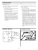
Page 1: ...reserved Revised 2003 REV D 753226 No part of this book shall be reproduced by any means electronic photocopying or otherwise without written permission from the publisher METAL DETECTOR KIT MODEL K 2...

Page 2: ...1 S1 Switch 541102 1 Solder Roll 24 551124 1 B1 Battery Snap 9V 590098 1 Wire 26 Enamel 45 846000 1 Resistor Transistor Capacitor PARTS IDENTIFICATION Switch Discap Battery Snap Trim Pot IDENTIFYING...

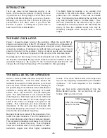
Page 3: ...illate at the LC resonance frequency By varying P1 the current through transistor Q1 will change thus forcing the frequency of the oscillator to change slightly Figure 1 C1 C2 R2 R1 B1 S1 Q1 P1 L1 THE...

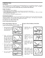
Page 4: ...mponent Lead Solder Soldering Iron Drag Foil 1 Solder all components from the copper foil side only Push the soldering iron tip against both the lead and the circuit board foil 2 Apply a small amount...

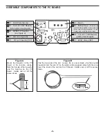
Page 5: ...Coil see Figure B C2 0015mF Capacitor 152 S1 Switch B1 Battery Snap Install the red wire into the positive hole and the black wire into the negative hole Solder and cut off the excess leads R2 4 7kW 5...

Page 6: ...bridge with your soldering iron 2 Be sure that all components have been mounted in their correct places a Use a fresh 9V battery b Be sure that the coil is soldered properly The two ends of the wire...

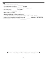
Page 7: ...n LC circuit has a coil and a ___________ 7 An inductor can be made by winding some wire into a ____________ 8 If part of the energy in the LC circuit in Figure 1 is fed to the emitter of Q1 the circu...

Page 8: ...ElencoTM Electronics Inc 150 W Carpenter Avenue Wheeling IL 60090 847 541 3800 http www elenco com e mail elenco elenco com...

Reviews: