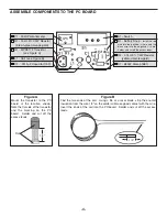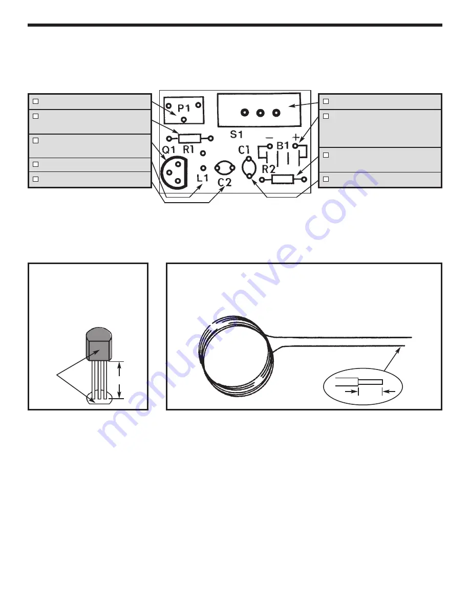
Figure A
Mount the transistor to the PC
board at the location shown.
Note the flat side of the transistor
and the marking on the PC
board.
Solder and cut off the
excess leads.
-4-
ASSEMBLE COMPONENTS TO THE PC BOARD
P1 - 50k
W
Potentiometer
R1 - 15k
W
5% 1/4W Resistor
(brown-green-orange-gold)
Q1 - MPS5172 Transistor
(see Figure A)
L1 - Coil (see Figure B)
C2 - .0015
m
F Capacitor (152)
S1 - Switch
B1 - Battery Snap -
Install the red
wire into the positive (+) hole and the
black wire into the negative (--) hole.
Solder and cut off the excess leads.
R2 - 4.7k
W
5% 1/4W Resistor
(yellow-violet-red-gold)
C1 - 680pF Discap (681)
Flat
Figure B
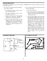
Find the two ends of the coil. Using a file or a razor blade, strip the enamel
insulation from the wire 1/4” so the solder will make good contact with the wire.
Insert the ends of the coil into the PC board. Solder and cut off the excess
leads.
1/4”
1/4”


