background image

Important:

If any parts are missing or damaged, 

DO NOT RETURN TO RETAILER

.  Call toll-free (800) 533-2441 or e-mail us at:

help@elenco.com.  Customer Service 

150 Carpenter Ave. 

Wheeling, IL  60090  U.S.A.

Qty.

ID

Name

Symbol

Part #

Qty.

ID

Name

Symbol

Part #


r

3

1-Snap Wire

6SC01


r

1

2.5V Lamp

6SCL1


r

5

2-Snap Wire

6SC02


r

1

Motor

6SCM1


r

3

3-Snap Wire

6SC03


r

1

Glow Fan

6SCM1FG


r

1

4-Snap Wire

6SC04


r

1

Phototransistor

6SCQ4


r

1

5-Snap Wire

6SC05


r

1

100

W

Resistor

6SCR1


r

1

Battery Holder - uses

2 1.5V type AA (not included)

6SCB1


r

1

Slide Switch

6SCS1


r

1

Base Grid

(11.0” x 7.7”)

6SCBG


r

1

Press Switch

6SCS2


r

1

Color LED 

SCD8


r

1


r

1

Speaker

6SCSP2


r

1

Egg LED Attachment

6SCEGG


r

1

Music

Integrated Circuit

6SCU1


r

1

Prismatic film

6SCFILM                                                                                                                                                                                                          


r

1

Alarm

Integrated Circuit

6SCU2


r

1


r

1

Jumper Wire (Black)

Jumper Wire (Red)

6SCJ1  

6SCJ2

r

1

Space War

Integrated Circuit

6SCU3

5

4

3

2

1

S1

S2

Q4

M1

U3

U2

U1

SP2

B1

L1

D8

R1

-2-

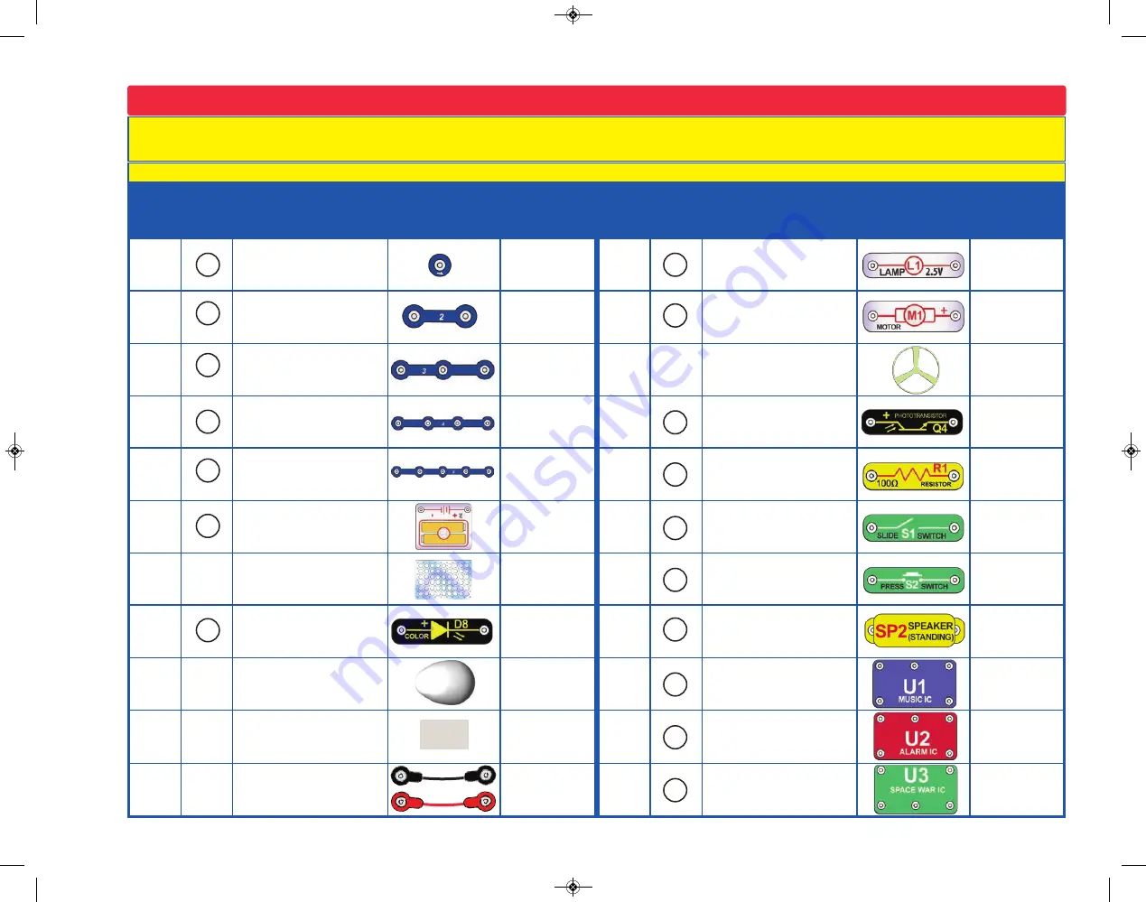
Parts List

(Colors and styles may vary) Symbols and Numbers


You may order additional / replacement parts at our website:  www.snapcircuits.net

SC-130_050115.qxp  5/14/15  11:45 AM  Page 3

Summary of Contents for Snap Circuits Jr. Select

Page 1: ...SC 130_050115 qxp 5 14 15 11 44 AM Page 1...

Page 2: ...d enable supervising adults to establish the experiment s suitability for the child Make sure your child reads and follows all of the relevant instructions and safety procedures and keeps them at hand...

Page 3: ...Resistor 6SCR1 r 1 Battery Holder uses 2 1 5V type AA not included 6SCB1 r 1 Slide Switch 6SCS1 r 1 Base Grid 11 0 x 7 7 6SCBG r 1 Press Switch 6SCS2 r 1 Color LED SCD8 r 1 r 1 Speaker 6SCSP2 r 1 Egg...

Page 4: ...stic base grid is included with this kit to help keep the circuit blocks properly spaced You will see evenly spaced posts that the different blocks snap into The base has rows labeled A G and columns...

Page 5: ...rical pressure pushing electricity through a circuit just like a pump pushes water through pipes This voltage is much lower and much safer than that used in your house wiring Using more batteries incr...

Page 6: ...S1 S2 connect pressed or ON or disconnect not pressed or OFF the wires in a circuit When ON they have no effect on circuit performance Switches turn on electricity just like a faucet turns on water fr...

Page 7: ...r circuit represents how much it resists the electrical pressure voltage and limits the flow of electric current The relationship is Voltage Current x Resistance When the resistance increases less cur...

Page 8: ...ids_creation Send your suggestions to ELENCO elenco elenco com ELENCO provides a circuit designer so that you can make your own Snap Circuits drawings This Microsoft Word document can be downloaded fr...

Page 9: ...ject 2 except initially use the speaker SP2 in place of the resistor the color LED should light Then replace the speaker with the resistor the LED should still light 6 Alarm IC U2 Build project 110 yo...

Page 10: ...ame 32 69 Using Parts as Conductors 32 70 Spin Draw 33 71 Singing Motor 33 72 Visual Volume 34 73 Eurosiren Volume 34 74 Funky Volume 34 75 Fire Light Siren 34 76 Crooks Cars 34 77 Static Gun 34 78 Po...

Page 11: ...2 AA batteries not included into the battery holder B1 if you have not done so already Turn on the slide switch S1 and Egg LED attachment Snappy says when you turn on the slide switch electricity flow...

Page 12: ...sound and LED Also push the press switch S2 to light the lamp L1 You can change the siren sound by shining a bright light on the phototransistor Q4 or covering it if the room light was already bright...

Page 13: ...electric current also flow through the speaker which produces sound The music IC produces the tune by adjusting the pattern of current bursts through the speaker Musical integrated circuits are used t...

Page 14: ...during operation Do not lean over the motor Use the preceding circuit but reverse the position of the motor M1 Push the press switch S2 to spin the motor and glow fan Here the glow fan is blowing air...

Page 15: ...doesn t fly off then press the switch several times rapidly when it is at full speed The motor spins faster when the batteries are new If you don t want the fan to fly off then reverse the orientation...

Page 16: ...is on top of the alarm IC U2 and adding three 2 snap wires around it as shown Project 15 Silly Sound Light Modify the project 13 circuit by removing the 2 snap wire and 1 snap wire that are on top of...

Page 17: ...Controlled Music Project 18 Build the circuit as shown When you place a metal paper clip across the snaps on the red black wires as shown in the drawing current flows from the batteries B1 through th...

Page 18: ...pace war IC You may need to be covering uncovering the phototransistor in a relatively dark room Photo Space War The upper right snap of the space war IC is like an electrical gate opening and closing...

Page 19: ...or push the press swtch S2 Do both several times and in combination Project 24 Super Photo Space War Project 25 Quieter Super Space War This circuit is just like project 23 but not as loud Activate it...

Page 20: ...tricity flows the brighter the lamp gets The motor needs the most electricity when it starts up making the lamp brightest Without the fan the motor can spin fast and needs little electricity making th...

Page 21: ...P Hear the Motor with Light Why does the motor make sound A motor uses magnetism to convert electrical energy into mechanical spinning motion As the motor shaft spins around it connects disconnects se...

Page 22: ...actually contains separate red green and blue lights with a microcircuit controlling them Each time the LED changes colors the voltage across it changes Each time the voltage changes you hear a click...

Page 23: ...but you will view it differently Turn on the switch S1 and view the LED through the prismatic film the clear slide Prismatic film makes interesting light Use the project 34 and 35 circuits but view t...

Page 24: ...Project 40 Loud Spin Sound Use the preceding circuit but replace the 100W resistor with a 3 snap wire Now the sound is louder In this project you changed the amount of current that goes through the sp...

Page 25: ...ath protects the electronic parts If fuses did not exist many parts could get hot and even start fires Replace the 3 snap wire and the circuit should return to normal Many electronic products in your...

Page 26: ...5 snap wire at positions A B or C and then pressing the press switch S2 If Player 2 places the red jumper wire at the correct position the sounds played indicates a hit He keeps guessing until he hit...

Page 27: ...he flicker resumes Project 47 Reflection Detector Build the circuit to the right Place it where there won t be any room light hitting the phototransistor Q4 such as in a dark room or under a table and...

Page 28: ...ections between A D and between Y B then make a connection between X A The circuit works the same way but now it sounds like a familiar song but with static A B C D Use the preceding circuit but add a...

Page 29: ...ll hear a siren and music together while the lamp L1 varies in brightness Modify the last circuit by connecting points Y Z with a 2 snap on level 5 The circuit works the same way but now it sounds lik...

Page 30: ...ace the speaker SP2 with the color LED D8 on top and away from U3 Build the circuit shown on the left and turn it on The lamp L1 alternates between being on and off while the speaker SP2 alternates be...

Page 31: ...police siren is heard and then stops Spin the motor and it will play again Note however that music can be heard faintly in the background of the siren Modify the last circuit by connecting points X Y...

Page 32: ...a T12 bulb 1 5 diameter that runs on normal house current Start the disc spinning and release the press switch S2 As the speed changes you will notice the white lines first seem to move in one direct...

Page 33: ...G The purple player in column 1 the blue player in column 2 the green player in column 3 and the yellow player in column 4 Spin the wheel by closing the press switch S2 The first single color wedge th...

Page 34: ...tain some thin and thick marking pens as drawing tools Spin the paper by pressing and holding press switch S2 down Press the marker on the paper to form rings To make spiral drawings release press swi...

Page 35: ...compare the sound Modify the last circuit by connecting points X Q using a 1 snap wire and a 2 snap wire Now you hear a European siren when enough light reaches the phototransistor Now add a 3 snap w...

Page 36: ...ff several times You hear static from the speaker SP2 when you turn the switch on or off Project 79 Crazy Combo Build the circuit shown Turn it on press the press switch S2 several times and wave your...

Page 37: ...ure the color LED D8 lights up But if you connect the free end of one of the 2 snaps to the high bar and the free end of the other 2 snap to the low bar then the color LED does not light up 36 Project...

Page 38: ...r several seconds and then goes off Uncover the photoresistor and place the unit near a light and the LED will light Cover the phototransistor again and the LED will turn off The resistance of the pho...

Page 39: ...in the electrical box You could also have more than two switches and the circuit would function the same way Project 87 This OR That This circuit is commonly called an OR gate OR gates are used in dig...

Page 40: ...rtant building block in computers This circuit is commonly called a NAND gate NAND gates are used in digital logic circuits to perform an inverted logical multiply When one of the inputs is low one of...

Page 41: ...and turn on the circuit Wetting your fingers improves the connection between the metal and your finger Turn the switch S1 on and the lamp L1 and color LED D8 start flashing You hear two different ton...

Page 42: ...after the LED lights Project 95 Fun with the Alarm IC Phototransistors can be used to control many devices such as street lights clock radio alarms night lights etc Place the fan on the motor M1 and t...

Page 43: ...water shown There will be sound when you push the press switch S2 or when the jumper wires are in the water Pushing the press swtich or placing the jumper wires out and then back in into the water wil...

Page 44: ...rcuit In the circuit the outputs from the alarm U2 and music ICs are connected together Build the circuit shown and then place the alarm IC U2 directly over the music IC U1 resting on two 1 snaps and...

Page 45: ...e telegraph which was widely used in the latter half of the 19th century It only had two states on or off that is transmitting or not transmitting and could not send the range of frequencies contained...

Page 46: ...4 turn the slide switch S1 on and notice that the lamp L1 is off after several seconds Place the unit near a light and the lamp turns on Cover the phototransistor again The lamp turns off The resistan...

Page 47: ...l noise as it spins which can confuse the color changing circuit in the color LED The lamp is just a simple light bulb and is not affected by the Turn on the slide switch S1 the lamp L1 and color LED...

Page 48: ...e Use the preceding circuit but remove the connection between B C and add a connection between A B Now it sounds like a fire engine Project 113 European Siren Use the preceding circuit but remove the...

Page 49: ...e loose ends of the jumpers unconnected for now There is one more part you need and you are going to draw it Take a pencil No 2 lead is best but other types will also work SHARPEN IT and fill in the s...

Page 50: ...u detected Also try holding the jumper wires with your fingers to see if your body can set off the alarm Project 124 Ambulance Water Alarm Modify the circuit in Project 122 by adding a 3 snap wire bet...

Page 51: ...C D x Y Use the preceding circuit but add the phototransistor Q4 across points X Y using a 1 snap wire the side of Q4 should be towards U3 Use the preceding circuit but replace the color LED D8 with...

Page 52: ...33 Super Symphony of Sounds This circuit is similar to to the preceding circuit but also adds the motor M1 and glow fan Note that the speaker SP2 does not snap on the battery holder B1 but is secured...

Page 53: ...52 Page 31 for Project 66 Page 32 for Project 68 SC 130_050115 qxp 5 14 15 11 47 AM Page 53...

Page 54: ...53 Notes SC 130_050115 qxp 5 14 15 11 47 AM Page 54...

Page 55: ...s Pro Model SC 500 with over 500 projects Snap Circuits Motion Model SCM 175 with over 165 projects Build over 300 projects Including AM Radio Water Detector Motion Detector Electronic Kazoo Burglar A...

Page 56: ...SC 130_050115 qxp 5 14 15 11 47 AM Page 56...

Reviews: