Project 86
Same or “NOT”
Although this circuit seems simple,
inverters or NOT gates are very
important in digital logic circuits.
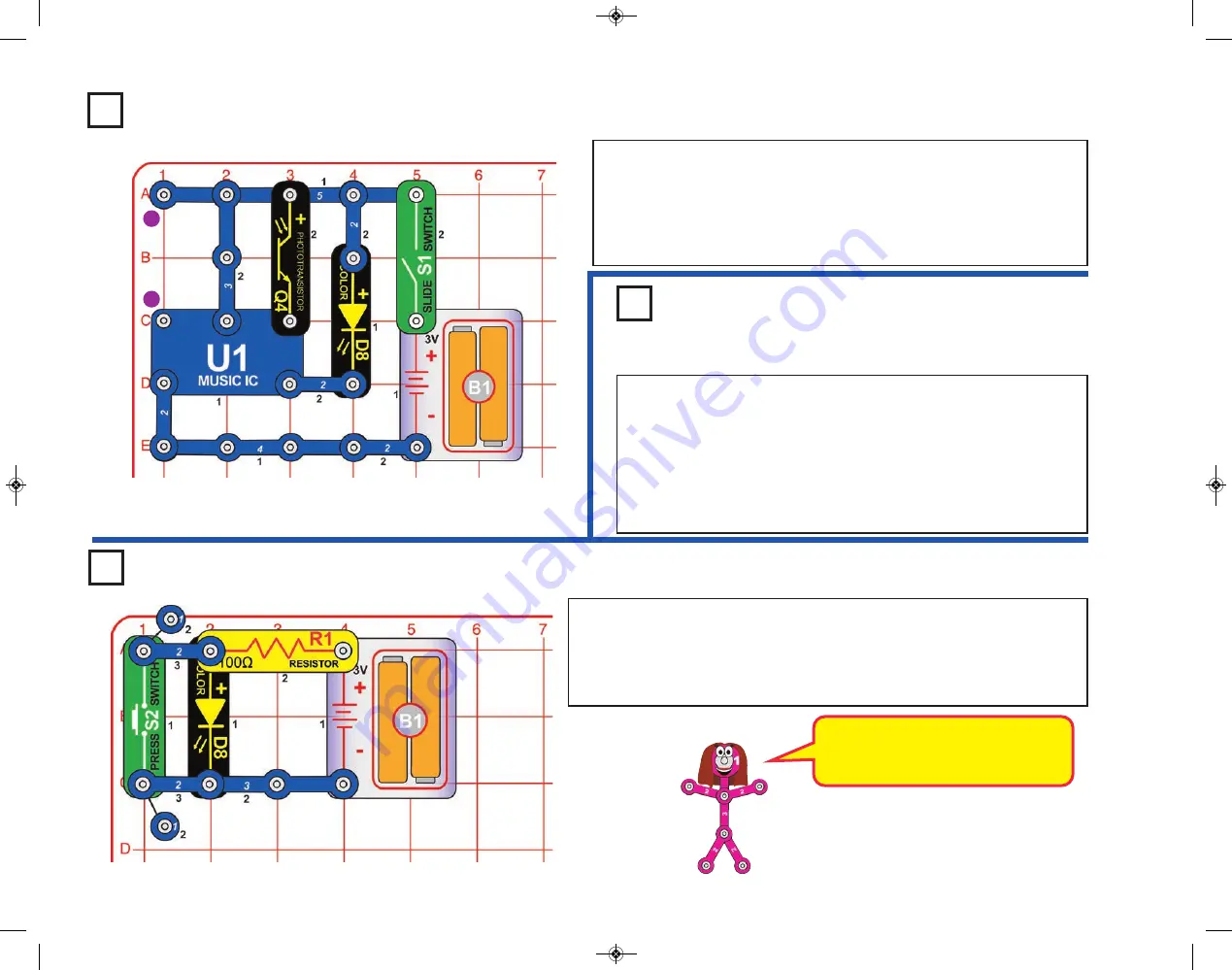
Build the circuit shown. Notice that when the press switch (S2) is pressed, the
color LED (D8) goes off. This is an example of an inverter circuit, or NOT gate.
Whenever the input is high (switch is on), the output is low (LED is off) and
whenever the input is low (switch is off) the output is high (LED is on).
Disassemble the circuit when finished to avoid draining your batteries.
Project 84
Light Makes Light
Project 85
Go & Glow
Build the circuit to the left. Cover the phototransistor (Q4), turn the switch
on, and notice that the color LED (D8) is on for several seconds and then
goes off. Uncover the photoresistor and place the unit near a light and the
LED will light. Cover the phototransistor again and the LED will turn off. The
resistance of the photoresistor decreases as the light increases activating
the U1 IC that varies the voltage to the LED making it light.
Use the proceding circuit, but connect the motor (M1) across points A
and B on the base grid, and remove the phototransistor (Q4). Turn the
switch on and the color LED (D8) lights for several seconds then goes
out. Turn the shaft of the motor and the LED will light again. As the
motor turns, it produce a voltage. There is a magnet and a coil inside
the motor. When the axis turns the magnetic field will change and
generate a small current through its terminals. This voltage then
activates the music IC.
-37-
A
B
2
SC-130_050115.qxp 5/14/15 11:46 AM Page 38


