MOUNT COMPONENTS TO THE SIDE PANELS
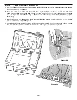
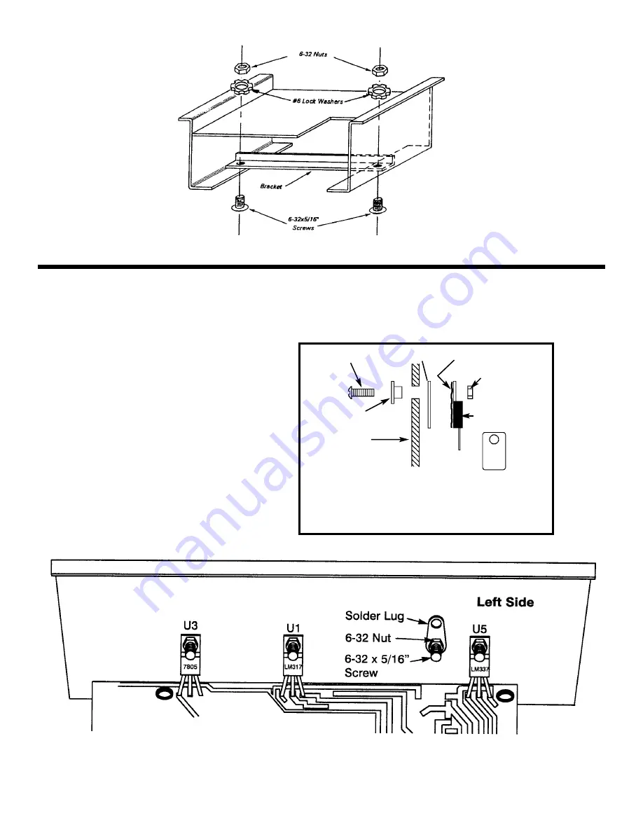
Mount U1, U3 and U5 to the left side panel as shown in Figure N. Insert the pins of each IC into the holes of
the PC board. Then, with the hardware shown in Figure M, attach each IC to the side panel. Solder the pins
of the ICs to the PC board.
r
U3 - LM7805
r
U1 - LM317
r
U5 - LM337
-10-
Mount the solder lug to the panel, as shown in Figure N, using a 6-32 x 5/16” screw and 6-32 nut.
r
Solder Lug
6-23 Nut
IC
* Silicone Grease
Mica
Side Panel
Insulator Washer
6-32 x 5/16” Screw
* Take a small amount of silicone grease from the
packet and apply it with a toothpick onto the back of
the ICs.
Mica
Figure M
Figure N
Figure L
Summary of Contents for XK-550K
Page 37: ...SCHEMATIC DIAGRAM ANALOG SECTION 36 ...
Page 50: ...SCHEMATIC DIAGRAM 49 ...


