-15-
RESISTANCE ANALYSIS OF POWER SUPPLY
Static testing of the power supply circuits. Do not plug the power supply into the 120VAC power supply
source until all resistance readings check out. The values given below are approximate.
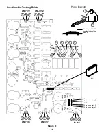
See Figure O for locations of testing points.
Resistance
From
To
Circuit
Ohms
Measured
1
Right Side Panel
Earth Ground
less than 1
Ω
2
3
On/Off Switch, Fuse
Infinite (SW1 Off)
2
3
On/Off, Fuse
7
Ω
(SW1 On)
4
5
12V Secondary
1.5
Ω
6
7
5V Secondary
1.2
Ω
8
9
Variable Voltage
1.6
Ω
10
GND 5-pin connector
+12V Regulator Input
greater than 20K
Ω
11
(com)
GND (V
Ω
) (5-pin connector)
--12V Regulator Input
greater than 20K
Ω
12
GND (B1)
+5V Regulator Input
greater than 20K
Ω
13
GND (B1)
+Variable Regulator Input
greater than 20K
Ω
14
(com)
GND (V
Ω
) (5-pin connector)
--Variable Regulator Input
greater than 20K
Ω
25
(com)
GND (V
Ω
) (5-pin connector)
Voltage ADJ +20V Regulator
CCW <1
Ω
CW >1.4K
Ω
26
GND (V
Ω
) (5-pin connector)
Voltage ADJ -20V Regulator
greater than 1.4K
Ω
27
GND (5-pin connector)
+5V Regulator GND
less than 1
Ω
28
GND (5-pin connector)
+12V Regulator GND
less than 1
Ω
29
GND (5-pin connector)
--12V Regulator GND
less than 1
Ω
10
15
+12V Regulator Input
less than 1
Ω
11
16
--12V Regulator Input
less than 1
Ω
12
17
+5V Regulator Input
less than 1
Ω
13
18
+Variable Regulator Input
less than 1
Ω
14
19
--Variable Regulator Input
less than 1
Ω
20
GND (5-pin connector)
+Variable Regulator Output
CCW 100
Ω
CW 2.12K
20
+20 (5-pin connector)
+Variable Regulator Output
less than 1
Ω
21
GND (5-pin connector)
--Variable Regulator Output
CCW 100
Ω
CW 2.12K
21
--20 (5-pin connector)
--Variable Regulator Output
less than 1
Ω
22
GND (5-pin connector)
+5V Regulator Output
greater than 5K
Ω
22
B4
+5V Regulator Output
less than 1
Ω
23
GND (5-pin connector)
+12V Regulator Output
greater than 5K
Ω
23
B3
+12V Regulator Output
less than 1
Ω
24
GND (5-pin connector)
--12V Regulator Output
greater than 5K
Ω
24
B2
--12V Regulator Output
less than 1
Ω
5
15VAC (5-pin connector right)
15VAC
less than 1
Ω
4
15VAC (5-pin connector left)
15VAC
less than 1
Ω
«
+30%
²
Note: meter lead polarity CCW - Counter Clockwise CW - Clockwise
µ
VR1 & VR2 Adjustment
²
²
µ«
µ«
«
«
20A 2A COM V
Ω
V
Ω
COM
Summary of Contents for XK-550K
Page 37: ...SCHEMATIC DIAGRAM ANALOG SECTION 36 ...
Page 50: ...SCHEMATIC DIAGRAM 49 ...


