-19-
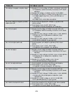
PROBLEM
POSSIBLE CAUSE
No voltage at negative variable output.
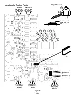
1. Measure for an AC voltage of 18VAC at cathode of D8, D10.
A. Transformer and/or secondary connection to PC board
defective.
2. Measure DC voltage of -28VDC at pin 2 of U5 LM337.
3. Set voltage for minimum -1.25VDC and measure pin 3 of U5.
A. Voltage adjusts only from -7.8 to -9.8V R2 open or
defective.
B. Voltage -27V, check VR2 connections.
No or low voltage at negative variable
1. Check to see if capacitor C5 1000
µ
F is inserted in the
output with load.
correct polarity.
2. Check ripple on pin 2 of U5. 6VP-P max.
A. Capacitor C5 and/or diodes D8, D10 defective.
No +12V at output.
1. Measure an AC voltage of 15VAC at anode of D1, D3.
A. Transformer and/or secondary connection to PC board
defective.
2. Measure for a DC voltage of 21VDC at pin 1 of U2 LM7812.
A. Diodes D1, D3 in backwards or defective, check
capacitor C1.
3. Measure for a DC voltage of 12VDC on pin 3 of U2.
A. U2 LM7812 defective or open ground.
No +12V at output with load.
1. Check capacitor C2 1000
µ
F is inserted in the correct
polarity.
2. Check ripple on pin 1 of U2. 7VP-P Max.
A. Capacitor C2 or diodes D1, D3 defective.
No -12V at output.
1. Measure an AC voltage of 15VAC at anode of D2, D4.
A. Transformer and/or secondary connection to PC board
defective.
2. Measure for a DC voltage of -21VDC at pin 2 of U4 LM7912.
A. Diodes D2, D4 in backwards or defective, check
capacitor C4.
3. Measure for a -12VDC voltage on pin 3 of U4.
A. U4 LM7912 defective or open ground.
No -12V at output with load.
1. Check capacitor C4 is inserted in the correct polarity.
2. Check ripple on pin 2 of U3. 7VP-P Max.
A. Capacitor C4 and/or diodes D1, D3 defective.
No +5VDC at output
1. Measure an AC voltage of 9VAC at anode of D5, D6.
A. Transformer and/or secondary connection to PC board
defective.
2. Measure for a DC voltage of 12VDC at pin 1 of U3 LM7805.
A. Diodes D5, D6 in backwards or defective, check
capacitor C3.
3. Measure for a 5VDC voltage on pin 3 of U3 LM7805.
A. U3 LM7805 defective or open ground.
No +5VDC at output with load.
1. Check that capacitor C3 is inserted in the correct polarity.
2. Check ripple on pin 1 of U3. 4VP-P Max.
A. Capacitor C3 and/or diodes D5, D6 defective.
Summary of Contents for XK-550K
Page 37: ...SCHEMATIC DIAGRAM ANALOG SECTION 36 ...
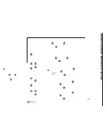
Page 50: ...SCHEMATIC DIAGRAM 49 ...


