-38-
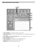
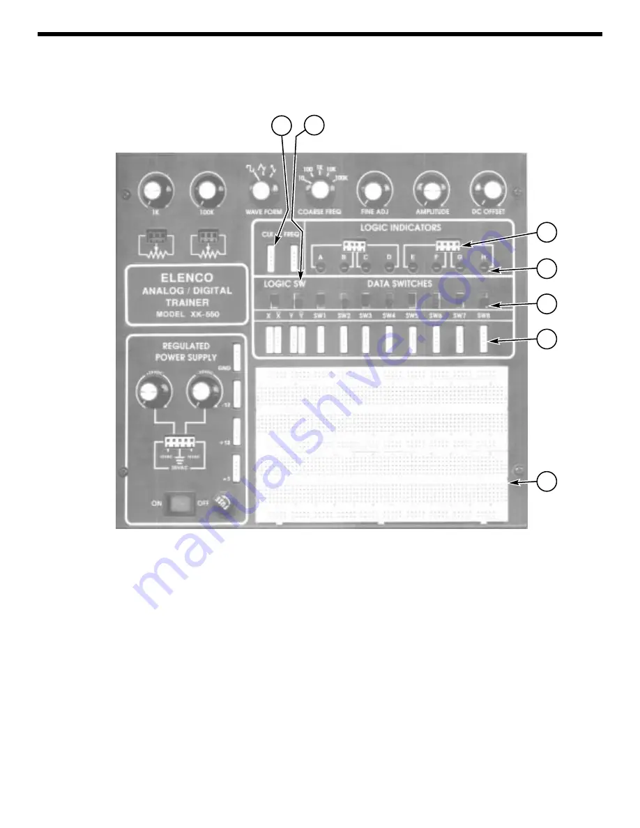
USERS DESCRIPTION OF FRONT PANEL
1. OUTPUT TERMINALS - For all functions as stated. 4 pins per block.
2. TWO LOGIC SWITCHES - These are no bounce logic switches. Give one signal state change per move-
ment of switch.
3. INPUT TERMINALS FOR LOGIC INDICATOR LEDs - “A” input corresponds with “A” lamp, etc.
4. LOGIC INDICATORS - Eight LEDs.
5. EIGHT DATA SWITCHES - Lets output of 5V or 0V depending on position.
6. OUTPUT TERMINAL - For all functions as stated. 4 pins per block.
7. BREDBOARD - One bredboard containing 730 tie points.
1
2
3
4
5
6
7
Summary of Contents for XK-550K
Page 37: ...SCHEMATIC DIAGRAM ANALOG SECTION 36 ...
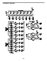
Page 50: ...SCHEMATIC DIAGRAM 49 ...

