CONTINUE
ê
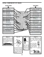
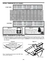
INSTALL COMPONENTS TO PC BOARD
START HERE
ê
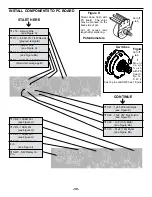
CONTINUE
ê
-41-
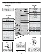
Figure C
Cut a piece of bare wire long
enough so that 1/4” of wire
passes through each hole in
the PC board after the wire is
formed (provided in the sec-
ond package).
Figure D
Insert the IC socket into the PC board
with the notch in the direction shown
on the top legend. Solder the IC sock-
et into place.
Insert the IC into the
socket with the notch in the same
direction as the notch on the socket.
Socket
IC
Notch
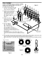
Figure B
Mount with the flat side of the
LED as shown on the top leg-
end side of the PC board.
Flat
Spacer
r
U9 - 14-pin IC Socket
r
U9 - 74HC04 IC
(see Figure D)
r
U8 - 14-pin IC Socket
r
U8 - 74HC04 IC
(see Figure D)
r
J19 - Jumper Wire
(see Figure C)
r
R15 - 220
Ω
5% 1/4W Resistor
(red-red-brown-gold)
r
J22 - Jumper Wire
(see Figure C)
r
J21 - Jumper Wire
(see Figure C)
r
J20 - Jumper Wire
(see Figure C)
r
R18 - 1K
Ω
5% 1/4W Resistor
(brown-black-red-gold)
r
U7 - 14 pin IC socket
r
U7 - 7403 IC
(see Figure D)
r
J24 - Jumper Wire
(see Figure C)
r
D25 - LED and Spacer
(see Figure B)
r
J27 - Jumper Wire
(see Figure C)
r
D24 - LED and Spacer
(see Figure B)
r
D23 - LED and Spacer
(see Figure B)
r
D22 - LED and Spacer
(see Figure B)
r
D21 - LED and Spacer
(see Figure B)
r
D20 - LED and Spacer
(see Figure B)
r
D19 - LED and Spacer
(see Figure B)
r
D18 - LED and Spacer
(see Figure B)
r
R19 - 1K
Ω
5% 1/4W Resistor
(brown-black-red-gold)
r
R16 - 1K
Ω
5% 1/4W Resistor
(brown-black-red-gold)
r
R17 - 1K
Ω
5% 1/4W Resistor
(brown-black-red-gold)
Summary of Contents for XK-550K
Page 37: ...SCHEMATIC DIAGRAM ANALOG SECTION 36 ...
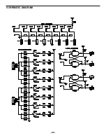
Page 50: ...SCHEMATIC DIAGRAM 49 ...


