-43-
RESISTANCE ANALYSIS OF DIGITAL SECTION
Place the top panel onto the unit. Static testing of the digital section circuits. Do not plug the power supply into
a 117 volt power source until all of the resistance readings check out. The values given below are approxi-
mate.
From
To
Switch Position
Ohms
Resistance Measured
SW1
GND
In down position
less than 1
Ω
SW2
GND
In down position
less than 1
Ω
SW3
GND
In down position
less than 1
Ω
SW4
GND
In down position
less than 1
Ω
SW5
GND
In down position
less than 1
Ω
SW6
GND
In down position
less than 1
Ω
SW7
GND
In down position
less than 1
Ω
SW8
GND
In down position
less than 1
Ω
SW1
GND
In up position
greater than 3K
Ω
SW2
GND
In up position
greater than 3K
Ω
SW3
GND
In up position
greater than 3K
Ω
SW4
GND
In up position
greater than 3K
Ω
SW5
GND
In up position
greater than 3K
Ω
SW6
GND
In up position
greater than 3K
Ω
SW7
GND
In up position
greater than 3K
Ω
SW8
GND
In up position
greater than 3K
Ω
SW1
+5V
In up position
less than 300
Ω
SW2
+5V
In up position
less than 300
Ω
SW3
+5V
In up position
less than 300
Ω
SW4
+5V
In up position
less than 300
Ω
SW5
+5V
In up position
less than 300
Ω
SW6
+5V
In up position
less than 300
Ω
SW7
+5V
In up position
less than 300
Ω
SW8
+5V
In up position
less than 300
Ω
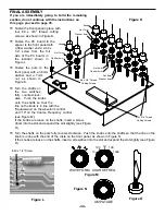
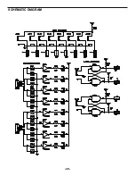
LOGIC SW
DATA SWITCHES
X X
Y Y
SW1
SW2 SW3
SW4 SW5
SW6 SW7
SW8
Summary of Contents for XK-550K
Page 37: ...SCHEMATIC DIAGRAM ANALOG SECTION 36 ...
Page 50: ...SCHEMATIC DIAGRAM 49 ...


