background image


24 

2.3.3 Specific Steps 

2.3.3.1 Login 

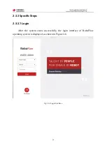
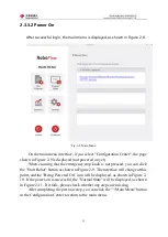
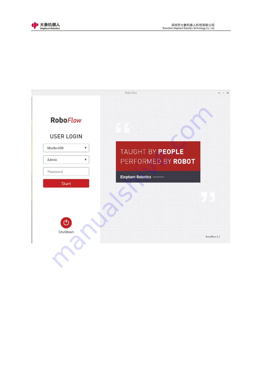
After  the  system  starts  successfully,  the  login  interface  of  RoboFlow 

operating system is displayed, as shown in Figure 2-6. 


Fig. 2-6 Login Interface 


Summary of Contents for myCobot Pro 600

Page 1: ...1 Elephant Robotics User Manual myCobot Pro 600 Language English Compiled in 2022 3 28...

Page 2: ...Ltd hereinafter referred to as Elephant Robotics In addition the product information and related resources mentioned in this manual are for reference only and the contents are subject to change withou...

Page 3: ...obot to the working position and fix it to the base according to the installation instructions Debugging Debugging the robot to work status Maintenance work regular maintenance robot system to ensure...

Page 4: ...nnable Project 22 2 3 1 Preparation Work 22 2 3 2 Flow Chart 23 2 3 3 Specific Steps 24 3 Product Introduction 36 3 1 Overview 36 3 2 Product Appearance and Composition 37 3 3 Working Principles and S...

Page 5: ...ons 53 5 1 1 Overview 53 5 1 2 Main interface introduction 54 5 1 3 Introduction to common tools 79 5 1 4 Function instruction 96 5 2 API Interface Description 126 5 2 1 Overview 126 5 2 2 Socket Stri...

Page 6: ...maximize personal safety and property safety This chapter provides a basic guide to safe use by introducing different safety alert symbols and precautions 2 Interpretation of related terms 1 Collabora...

Page 7: ...operator may still occur Therefore it is very important to understand the safety hazards of robot use which is beneficial to prevent problems before they occur Tables 1 2 4 below are common safety haz...

Page 8: ...r If the clamped object is not removed it may cause danger such as people being injured by crashing 6 There is a risk of accidental movement of the robot Under no circumstances should you stand under...

Page 9: ...one responsible for installing and maintaining the robot must read and follow these safety instructions 2 Ensure that safety measures and robot safety configuration parameters are defined as required...

Page 10: ...box 11 After the operation is completed the safety protection door should be closed immediately and the various switches of gas and electricity should be closed according to the procedure and the work...

Page 11: ...erated correctly to prevent electric shock As shown in Figure 1 2 A power proof warning label is attached to the power box to remind the operator that there is a potential danger of electric shock to...

Page 12: ...ke When it is in an emergency stop state normal if the robot system is to be placed in an emergency stop state press the emergency stop switch when the robot does not operate Before using the emergenc...

Page 13: ...ion under guidance In addition you can set the protection threshold for each movement and each movement of the robot and set the two protection threshold directions including the X Y plane horizontal...

Page 14: ...14 2 QuickStart 2 1 Installation Instructions for the Robot Arm 1 Full unpacked items of robot arm...

Page 15: ...15 2 Pedestal mounting 1 Install M6X16 screws to fix the baseplate on the table 2 An effect picture of the completed installation...

Page 16: ...16 3 Place the pedestal of the robot arm on the fixed baseplate 4 Remove the set screws of housing from the pedestal of robot arm...

Page 17: ...17 5 Open the housing of the pedestal of robot arm and fix the the pedestal and baseplate of robot arm with M6X16 screws...

Page 18: ...18 6 After installation buckle the housing of the pedestal of robot arm 7 Install the set screws of housing for the pedestal of robot arm...

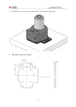
Page 19: ...19 8 Install the set screws of housing for the pedestal of robot arm 9 Baseplate dimension figure...

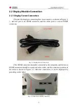
Page 20: ...nnector and the other port is a micro HDMI connector Fig 2 1 Display Screen Connection 2 The HDMI connector should be connected to the computer and the micro HDMI connector should be connected to the...

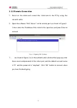
Page 21: ...own in Figure 2 3 then enter the IP address of the robot in the input box and press Enter to connect Fig 2 3 Opening VNC Software 1 As shown in Figure 2 4 in the authentication window that pops up ent...

Page 22: ...ns 1 Check that the robot arm is in perfect condition and undamaged 2 Install the fixed robot arm 3 Connect the power adapter and provide the appropriate voltage 4 Connect the visual devices displayer...

Page 23: ...e program editing flow chart as shown in Fig 2 5 Start Login New blank program Add and edit instructions Program debugging Save and run the program End Does it meet the preset requirements YES NO Powe...

Page 24: ...24 2 3 3 Specific Steps 2 3 3 1 Login After the system starts successfully the login interface of RoboFlow operating system is displayed as shown in Figure 2 6 Fig 2 6 Login Interface...

Page 25: ...nd a pop up window will appear as shown in Figure 2 7 Fig 2 7 Input Keyboard The default login password of the user name Admin is elephant please enter the corresponding login password if you select o...

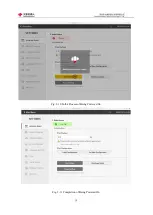
Page 26: ...stop knob is not pressed you can click the Start Robot button as shown in Figure 2 9 The interface will change at this point and the Being Powered On icon will be displayed as shown in Figure 2 10 If...

Page 27: ...27 Fig 2 9 State of Being Not Powered On...

Page 28: ...28 Fig 2 10 In the Process of Being Powered On Fig 2 11 Completion of Being Powered On...

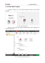
Page 29: ...in Figure 2 12 click Write Program and then select Blank Program Fig 2 12 Select Blank Program After the previous step the program editing interface will be displayed as shown in Figure 2 13 Fig 2 13...

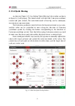
Page 30: ...lled to move along the direction of Cartesian coordinate system by clicking the button corresponding to the direction of Cartesian coordinate system Note that before using Cartesian control you need t...

Page 31: ...the quick moving tool to manually operate the robot control the robot movement to a certain pose return click Save the Current Point The teaching steps of the two points are the same If you need to ve...

Page 32: ...nue to run click Next The Run function corresponds to automatically running the program once In Advanced Functions you can set the number of times the loop runs or you can run the loop indefinitely Yo...

Page 33: ...ing Program in Manual Mode If you use manual mode to debug the program you need to press on the Press Down button to continue running If you release the button the program pauses and press it again to...

Page 34: ...n to make the robot arm enter the free movement mode and at this time you can move joint 1 joint 2 and joint 3 and if you need to move joint 4 joint 5 and joint 6 you need to press the ATOM button at...

Page 35: ...35...

Page 36: ...ching oriented and commercially developed machine assistant for Elephant Robotics It has rich extension interfaces supports a variety of development languages is easy to get started visual programming...

Page 37: ...37 3 2 Product Appearance and Composition Fig 3 1 Product Composition...

Page 38: ...38 3 3 Working Principles and Specifications 3 3 1 Working Space...

Page 39: ...39 3 3 2 Coordinate System DH parameters and coordinate system Fig 3 2 DH Coordinate System...

Page 40: ...40 Fig 3 2 DH Coordinate Parameter...

Page 41: ...e direction of the joint Cartesian coordinate movement Taking the coordinate system x0 y0 z0 in Figure 3 2 as the standard the X axis is perpendicular to the forward direction of the fixed base the Y...

Page 42: ...should be consistent and the end point should be reached at the same time 3 3 3 2 MoveL In rectilinear movement the path from point A to point B is straight as shown in Figure 3 4 Fig 3 4 MoveJ and M...

Page 43: ...movement Joint 1 180 180 Joint 2 270 90 Joint 3 150 150 Joint 4 260 80 Joint 5 168 168 Joint 6 174 174 Maximum movement velocity 115 degrees per second Repeated positioning accuracy 0 5mm Power voltag...

Page 44: ...44 3 4 2 Size Parameters Size parameters of myCobot Pro 600 are shown in Figure 3 9 and the end size parameters are shown in Figure 3 10 Fig 3 9 Size Parameters of myCobot Pro...

Page 45: ...45 Fig 3 10 Size Parameters of End Mounting Hole...

Page 46: ...cal Interfaces 4 1 1 Introduction to Base Electrical Interfaces 1 Figure 4 2 shows the electric in the front of base Fig 4 1 Front View of the Base 2 Figure 4 2 shows the interfaces on the left side o...

Page 47: ...47 3 Figure 4 3 shows the electrical interfaces on the base Fig 4 3 Right Side View of the Base 4 Figure 4 4 shows the electrical interfaces on the upside of the base Fig 4 4 Top View of the Base...

Page 48: ...9 OUT4 PNP Digital output signal 4 10 OUT5 PNP Digital output signal 5 11 OUT6 PNP Digital output signal 6 12 GND GND GND 13 Emergency stop ES1 External emergency stop control loop 14 ES1 15 Upside M...

Page 49: ...terface It is the port for the network data connection and users can use Ethernet interface for communication interaction between PC and robot system also can use it for Ethernet communication with ot...

Page 50: ...nd ensure that the switch circuit of the emergency stop is connected 8 MicroHDMI display interface Users can connect the MicroHDMI display interface to display the operation page to other device termi...

Page 51: ...4 5 shows the side interfaces at the end of the robot arm Fig 4 5 Electrical Diagram of Robot Arm End 4 2 2 End Electrical Specification 1 Tool I O interface Here s the tool I O drawing as shown in th...

Page 52: ...same as that of the bottom I O interface Serial No Signals Explanation Color of Matching Line M8 1 GND DC24V negative electrode White 2 OUT1 Tool output interface 1 Brown 3 OUT2 Tool output interface...

Page 53: ...f the time is achieved by using the raspberry operating system For example since the raspberry operating system runs in the teach pendant the user can use the carrier of the teach pendant to perform m...

Page 54: ...As shown in the login page TAUGHT BY PEOPLE PERFORMED BY ROBOT this is the concept that the elephant robotics has always insisted on making the operator become the commander of the robot Let robots re...

Page 55: ...ttings including operator accounts By clicking on the Shutdown button the RoboFlow operating system can be turned off and then the power supply can be turned off thus the robot system can be shut down...

Page 56: ...ease pay attention to saving the program It is suggested that the program be debugged in the trial run mode before the first run so as to avoid collision caused by point or path inconsistencies with e...

Page 57: ...ntrol bar Figure 2 3 Program editing window option Users can enter the program window by loading the program they need to run In this window users can 1 Get the basic information of the current ready...

Page 58: ...program Figure 2 4 Program Editing Window Options The user selects one as needed and then enters the program editing page as shown in Figure 2 5 When first entering the program edit page the user sees...

Page 59: ...interface At the same time users are allowed to teach points create new variables view IO view logs set important parameters and add functional instructions debugging programs and so on Function bar P...

Page 60: ...ptions bar A File As shown in Figure 2 7 you can edit the program file There are several operation options Save Save As New Load Rename and Exit Figure 2 7 File option bar B Edit As shown in Figure 2...

Page 61: ...h the point Then the Quickmove tool in the toolbar can be selected to manually operate the robot to move to the position Figure 2 9 Tool options bar 2 Functional Editing Window The RoboFlow operating...

Page 62: ...ill form a trajectory when you run the program b Gripper The user can use this function to set the end effector For example it holds the workpiece or releases the workpiece c Wait Users can use this f...

Page 63: ...e Halt The user can use this function to control the program to pause stop restart and pop up the window to display the corresponding prompt information f Switch The user can use this function to mak...

Page 64: ...nd can also use script programming to complete more complex tasks d Popup Users can use this function to customize the pop up window to display related information This helps the operator to analyze t...

Page 65: ...shown in Figure 2 14 The upper part is the name of the currently open program file and the lower part is the program tree which records the specific instructions and related information Figure 2 14 P...

Page 66: ...and disabling are also provided here 4 At the bottom of the program editing page there is a program running control bar as shown in Figure 2 16 When debugging a program users can use it to run pause s...

Page 67: ...he statistical report window is divided into four sub windows As shown in Figure 2 17 the general class counts the total running time the number of active programs and the specific information of acti...

Page 68: ...during the user s use of RoboFlow operating system This information helps users to determine what changes and feedback the system has made during the operation of the RoboFlow operating system In par...

Page 69: ...69 Figure 2 19 Log statistics As shown in Figure 2 20 security statistics can help users to count security related information such as collision information number of stops etc...

Page 70: ...ialization The initialization configuration page is shown in Figure 2 21 When robot movement is required the user needs to enter the configuration center initialize the robot or shut down the robot In...

Page 71: ...71 Figure 2 21 Initialization 2 Default program Figure 2 22 shows the default program settings page...

Page 72: ...actions to complete the specified task If the user does not want the system to start and the startup program starts running you can choose not to run This function is mainly for the program that the u...

Page 73: ...on update settings page Figure 2 23 Version update This page allows users to update the RoboFlow operating system in two ways one for local file updates and one for network updates 4 Account managemen...

Page 74: ...ds on this page On this page the user can get all the account information 5 Language and unit The language and unit settings page are shown in Figure 2 25 At present the RoboFlow operating system supp...

Page 75: ...75 Figure 2 25 Language and unit 6 Time Figure 2 26 shows the time setting page...

Page 76: ...er the calibration interface The calibration interface will appear in sequence with four circles as shown in the figure The user needs to click the center of the circle with a touch pen and each time...

Page 77: ...bration failure At this point you can confirm to exit the calibration interface and return to the page in Figure 2 27 to recalibrate 2 27 Touch Screen 8 About us As shown in Figure 2 28 it is about ou...

Page 78: ...formation about the operating system of the RoboFlow operating system For example the model of the robot used is the Elephant series version information and so on For more information please visit the...

Page 79: ...nually Therefore every user must be very familiar with the use of Quickmove using methods The wrong operation may result in damage to the robot and its peripheral equipment and even injuries to person...

Page 80: ...tal plane while the z axis is a plumb line Their positive direction is in accordance with the right hand rule that is holding the z axis with the right hand When the four fingers of the right hand tur...

Page 81: ...rection of the Cartesian coordinate system a x y z b Rx Ry Rz Figure 3 3 Cartesian coordinate system motion control mode button It should be noted that if the coordinate control button is pressed and...

Page 82: ...ws the robot to move until the user releases the button and the robot stops For example if you press the X direction motion control button you need to hold the button all the time The time of pressing...

Page 83: ...rs to the speed of the manual manipulation robot including continuous motion control speed and stepping motion control speed Please choose the right speed according to the actual needs If you are not...

Page 84: ...re 3 8 Return 9 Joint control Serial robot is an open kinematic chain of the robot It is formed by a series of connecting rods connected in series with a rotating joint or a moving joint The elephant...

Page 85: ...ections and the angle data of each axis can be seen Figure 3 9 Joint motion mode control window 10 Coordinate position As shown in Figure 3 10 this window displays the coordinate position correspondin...

Page 86: ...icked for reset 5 1 3 2 Installation As shown in Figure 3 11 there are three submenus inside the installation tool It is used to implement the loading saving installation configuration security config...

Page 87: ...in Figure 3 12 set the torque limit and brake control of the elephant robot Figure 3 12 Security configuration 3 Network Configuration As shown in Figure 3 13 configure the IP address and port number...

Page 88: ...88 Figure 3 13 Network settings...

Page 89: ...14 the input and output signals can be configured and monitored in this window and the output signals can be forcibly output IO configuration files can also be saved and loaded on this page As shown i...

Page 90: ...supply It can be determined whether the input is active high or active low according to the common configuration hardware connection determines 24V or 0V As shown in Figure 3 16 when the common termin...

Page 91: ...N2 IN3 COM1 Press the switch Press the switch No switch pressed No switch pressed Output Input Figure 3 16 Input signal application diagram As shown in Figure 3 17 the output is 24V when there is no o...

Page 92: ...editing As shown in Figure 3 19 there are 5 types of editable variable types They are string variables pose variables floating point variables integer variables and Boolean variables On this page you...

Page 93: ...r information and alarm information in the running log window Click the Information Warning and Error buttons to sort the corresponding logs Users can save logs to a local folder Log files are a recor...

Page 94: ...As shown in Figure 3 21 the basic settings page provides a common setting channel allowing the user to quickly set up some functions such as free movement related parameter settings even when leaving...

Page 95: ...95 Figure 3 21 Basic Settings...

Page 96: ...mand you can only choose one 1 Absolute point The absolute point is a description of the actual pose of the robot That is as long as the robot records the absolute point the next time the instruction...

Page 97: ...bsolute points namely Cartesian coordinate system coordinate values and joint angles Among them the Cartesian coordinate system coordinate value records the position and attitude of the robot TCP rela...

Page 98: ...erations press and hold the button until the robot moves to the current teaching point C Clear saved points If the current teaching point is no longer needed this button is used to clear the current t...

Page 99: ...99 Figure 4 3 Advanced configuration 2 Relative point Figure 4 4 shows the specific configuration page of the relative point...

Page 100: ...movement As shown in Figure 4 5 you can directly enter the coordinate value joint angle Directly enter coordinate values Directly input joint angle Figure 4 5 Two forms of direct input Regardless of w...

Page 101: ...the actual pickup and placement process other instructions such as setting instructions may be added between the two instructions to open the gripper Transition point Target placement Up Up Down Unit...

Page 102: ...e point can use the location of other waypoints Figure 4 7 shows the specific configuration page of the share point Figure 4 7 Shared point 1 Shared point Select the point you want to share in the box...

Page 103: ...the specific configuration page of the variable point 1 Variable assignment The user can select the associated pose variable and Move to this point can check whether the pose is the target pose 2 Adva...

Page 104: ...shown in Figure 4 10 the gripper can be named and multiple input signals can be controlled simultaneously What needs to be set is Set the number of output signals that need to be controlled select th...

Page 105: ...e saved state 1 Fully open The option in the execution gripper definition is the open state 2 Completely off The option in the execution gripper definition is off status 3 Debug control 1 Open the gri...

Page 106: ...ons 1 Waiting time The delay time can be set in seconds 2 Waiting for the input signal The state of the input signal is judged and waits until it meets the set input signal state condition 3 Waiting f...

Page 107: ...f selection 1 Set IO Set the state of the output signal In addition to selecting the set output signal to determine whether it is on or off you can also set the time that the signal is held 2 Set cond...

Page 108: ...108 Figure 4 12 Set 5 1 4 1 5 Group As shown in Figure 4 13 the group instructions provide common combination templates such as grabbing and placing combinations...

Page 109: ...programs or they can add or delete instructions freely according to their needs The user can simplify the process of finding instructions by using the group instruction And it is more convenient and...

Page 110: ...d the data determine and determine what to do next If Else can be used to determine the I O signal and can also be used to determine other conditions If Else consists of three parts If Else If and Els...

Page 111: ...Else If judge the determined conditions and Else corresponds to all cases except the above conditions 3 There can be more than one Else If but there is only one If and if you choose to add Else you c...

Page 112: ...orresponding block will be executed that is the robot will move to the waypoint 3 5 1 4 2 3 Subprogram As shown in Figure 4 17 other subroutines can be called using this instruction The main program c...

Page 113: ...113 Figure 4 17 Subprogram Figure 4 18 Display subroutine...

Page 114: ...unning interval of threads Note that motion instructions are not allowed in threads Figure 4 19 Thread 5 1 4 2 5 Halt The pause command is used to control the robot to pause stop and resume Figure 4 2...

Page 115: ...gram runs to this instruction it will start running again from the first instruction at the beginning Figure 4 20 Halt 5 1 4 2 6 Switch As shown in Figure 4 21 the conditional selection instruction is...

Page 116: ...example to judge the integer variable A set two cases if A is 1 execute the first route instruction if A is 2 execute the second route instruction If only a few variables are judged and other cases a...

Page 117: ...to these points As shown in Figure 4 22 you can select a line plane cube discrete point Figure 4 22 Pallet type Selection As shown in Figure 4 23 after you select line select the number of points and...

Page 118: ...Line As shown in Figure 4 24 after selecting Plane select the number of points of the two axes and the plane is divided equally These points are the dividing points This plane is determined by teachi...

Page 119: ...24 Plane As shown in Figure 4 25 after selecting Cube select the number of points of the three axes and the cube is divided equally These points are the dividing points Determine this cube by teaching...

Page 120: ...e instruction is run it moves to the nth point Until all the points have arrived the robot will start again from the first point Note that if you need to control the position of the robot to reach eac...

Page 121: ...t 5 1 4 3 2 Assign to var As shown in Figure 4 27 this command can assign values to integer variables and string variables You can also use the set variables to directly set the value of the variable...

Page 122: ...an be used to edit complex instructions providing a richer set of functional instructions Figure 4 28 shows the specific configuration page of the script command There are two types of setup scripts o...

Page 123: ...f pop up windows information warnings and errors The user selects one and customizes the pop up content There are also three kinds of pop up window control continue the program logging that is do not...

Page 124: ...allows the user to set up a TCP IP connection Figure 4 30 shows the specific configuration page of the Sender instruction If the robot system acts as a client the IP address filled in is the IP addre...

Page 125: ...rresponds to the port number assigned to the client device Click on the monitor button at which point the client device can connect to the robot system In the client list you can view the IP addresses...

Page 126: ...oint1_angle joint2_angle joint3_angle joint4_angle joint5_angle joint6_angle speed Example set_angles 10 0 11 0 12 2 12 3 11 1 16 0 500 the return string is formated in key value pair the key is the f...

Page 127: ...umber example get_digital_out 1 the return string is formated in key value pair the key is the funciton name the value is the value from robot like this get_digital_out 1 If any error occurred you wil...

Page 128: ...1 0 1 1 means in negative direction 1 means positive direction 0 means stop the return string is formated in key value pair the key is the funciton name the value is the value from robot like this jo...

Page 129: ...ide down Socket string format set_upside_down up_dn example set_upside_down 1 1 means upside doen 0 means not the return string is formated in key value pair the key is the funciton name the value is...

Page 130: ...air the key is the funciton name the value is the value from robot if the robot is running you will get check_running 1 if the robot is not running you will get check_running 0 If any error occurred y...

Page 131: ...occurred you will get set_payload error_message 29 set the acceleration of the robot Socket string format set_acceleration acc example set_acceleration 50 the acceleration must be an integer the unit...

Page 132: ...il the previous command finish the return string is formated in key value pair the key is the funciton name the value is the value from robot if success wait_command_done 0 If any error occurred you w...

Page 133: ...e Blank Program 2 Start to Monitor As shown in Figure 5 87 by clicking Tools Configuration and Network Serial Port in sequence you can enter the API monitor page You can enter the IP address of the TC...

Page 134: ...your PC terminal and click Client at the top of the software to enter the network setting page The server address and port number can be the values set in RoboFlow and then you can click TCP connecti...

Page 135: ...135 Fig 5 88 Connect to RoboFlow Fig 5 89 Connected Successfully...

Page 136: ...As shown in Figure 5 90 just by entering the Socket API that you want to send in the data window and clicking Send the received information will be displayed in the sending and receiving records Fig 5...

Reviews: