User Manual
EM303B General Purpose Inverter
117
frequency 0, the parameters of speed PID are P1, Ti1 and Td1, and above switching
frequency 1, the parameters of speed PID are P2, Ti2 and Td1. If switching frequency
1( F5-06)
>
switching frequency 0 (F5-05), then the process is linear transition process from
switching frequency 0 to switching frequency 1, as shown in Figure 7-17.
1. Be careful to edit the parameters of F5-00
~
F5-06.
2.When setting switching frequency, switching frequency 0(F5-05)≤switching
frequency 1(F5-06).
Torque control (SVC1)
EM303B could conduct torque control in SVC1.
When EM303B runs in SVC1 mode, torque control function refers to the occasions when
the excitation current of motor is in current closed-loop, the actual motor speed can be
estimated in real time through the internal motor magnetic flux and the speed estimation
function of inverter, thus motor torque current can be actively controlled. Furthermore, the
output torque of output motor can be controlled.
When EM303B runs in SVC1, the maximum output frequency is limited by torque control
upper limit frequency (F5-14). When the setting torque of inverter is bigger than the load
torque, the output frequency rises. When the output frequency reaches the upper limit
frequency of torque control, inverter always runs as per upper limit frequency, and when
the setting torque of inverter is less than the load torque, the output frequency drops.
No.
Function
Range
Unit Default Type
F5-07
Torque Current Acceleration Time
0.000
~
30.000
S
0.040
●
F5-08
Torque Current Deceleration Time 0.000
~
30.000
S
0.040
●
F5-07
Time taken for torque current to rise from 0 up to rated torque current.
F5-08
Time taken for torque current to drop from rated torque current down to 0.
No.
Function
Range
Unit Default Type
F5-09
Power Torque Current Limit
80.00
~
250.00
% 165.00
●
F5-10
Brake Torque Current Limit
80.00
~
250.00
% 165.00
●
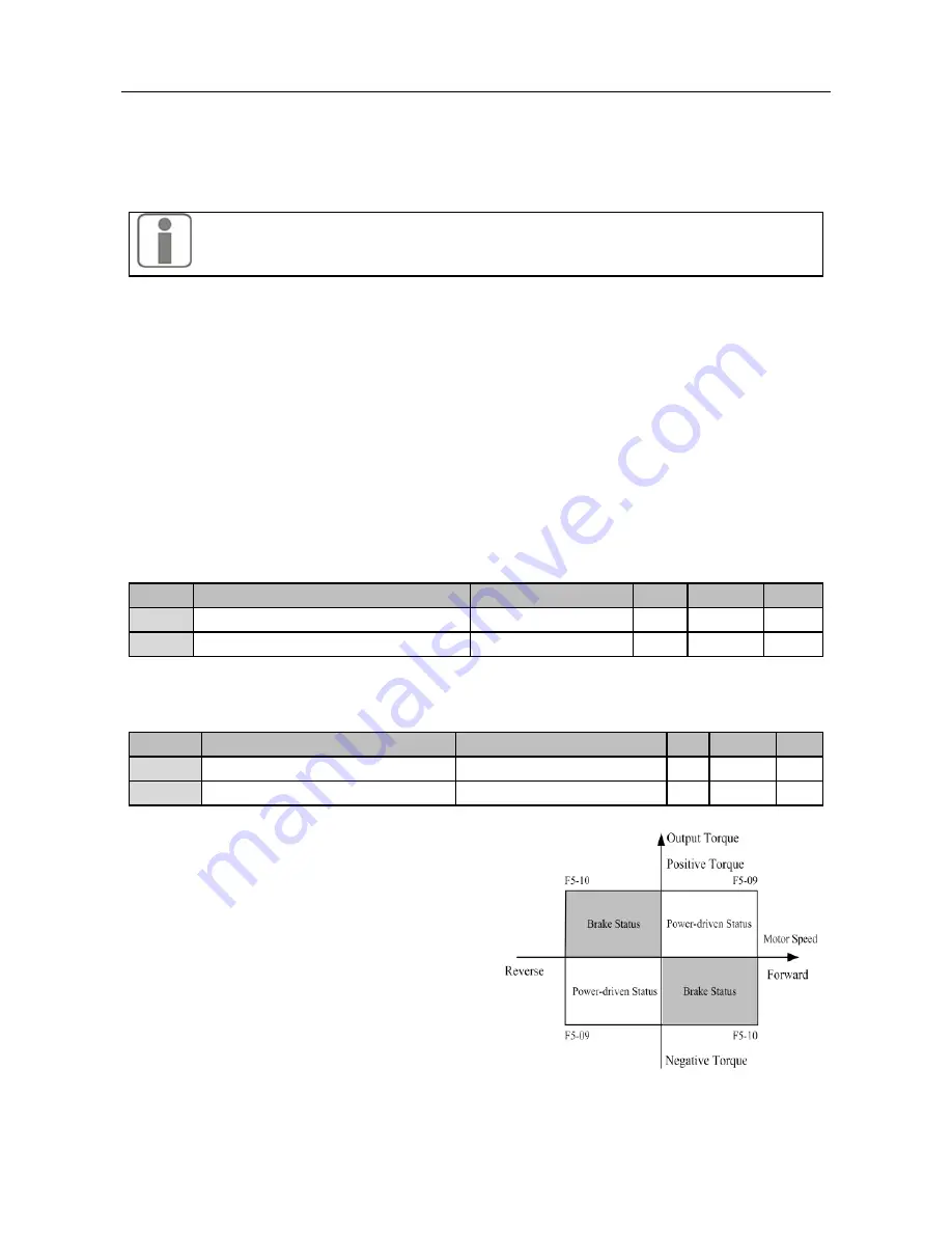
F5-09 and F5-10 are for setting the current
limit condition. If the output current of
inverter
>
the setting values of F5-09 and
F5-10, current limit is enabled, thus the
output current can be controlled within
current limit.
★
The parameters refer to the ratio of the
output current (at current limit) to the
rated output current of inverter.
★
Customer can setthe current limit based
on actual needs to protect motor or meet
the working requirements.
F5-09 and F5-10 limit the torque limiting
Figure 7-18
Current Limit of Power /Braking Torque


