User Manual
EM303B General Purpose Inverter
148
FC-21
Overcurrent Stall Proportion Gain IKp 0.00
~
100.00
0.10
〇
FC-31
Integral Time of Overcurrent Stall
0.00
~
300.00
mS
20.00
〇
Current limit control
FC-07 =0 Disabled
FC-07 =1 Not used
FC-07 =2 Enabled
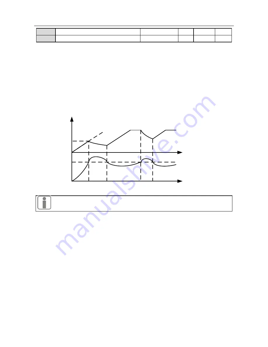
In the process of operation, when the current of motor which is on load reaches overcurrent
stall current (Set by FC-08), if overcurrent stall protection mode is enabled, system will start
overcurrent stall protection , it will lower output frequency for limiting the rising output
current, enable inverter runs at overcurrent stall status. When output current drops and is less
than overcurrent stall current, inverter return previous running status. See Figure 7-33 for
overcurrent stall enabling process.
Output Frequency
Output Current
(%)
Stall Current
Point
Time(S)
Time(S)
Figure 7-33 Overcurrent Stall Enabling Process
Overcurrent stall is only enabled in V/F control mode. It is recommended for the
applications with big inertia, fans, or multi-motor driven by single-inverter.
8.13.5
Overcurrent Stall Current
FC-08
is for setting overcurrent stall current. If the output current of inverter> the setting
value of FC-08, the overcurrent stall control is enabled for controlling the output current< the
setting value of FC-08.
FC-08 refers to the ratio of output current to the rated output current of inverter.
Users can set overcurrent stall current to protect motor or to meet application
requirements.
8.13.6
Current Limit Coefficient of Weak Flux
FC-09
is applied to limit inverter’s output current when the motor is operating in flux
weakening, to ensure the best output power when the motor accelerates or decelerates in flux
weakening.
8.13.7
Overcurrent Stall Parameters
FC-21 and FC-31 are the auto-regulation parameters of internal overvoltage protection. They
are used for after-sales regulation. The defaults can meet most of application needs.


