18
EN
DD52R-E-RF
Electronic position indicators
Data transmission via radio frequency
Models all rights reserved in accordance with the law.
Always mention the source when reproducing our drawings.
3. Assembly
1. Drill a Ø 6x10 mm hole in the body of the machine with a 30 mm centre
distance from the shaft to fit the rear referring pin.
2. Fit the indicator onto the shaft and make sure that the referring pin fits into the
hole.
3. Clamp the bushing to the shaft by tightening the grub screw with hexagon
socket and cup end, according to UNI 5929-85.
4. Turning on the system
After you have read and understood the section “Safety Instructions”, proceed by
switching on the indicator.
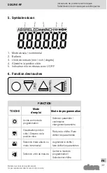
To turn the indicator on hold
then press the key
.
The display will light up and the indicator will be ready to be used.
4.1 Turning off the system
(only for storage)
To turn the system off enter the programming mode, select the
rESEt
parameter
then press the key
. At this point, press the button
and then press the
key; the display will turn off and the indicator will go into low power mode
of the battery.


