background image

User man


4.2.3 

P

Us
M
To
To
To


  F


FT


FT


O
M
no
Co
Pr
 
Cl
M
m
Co
Pr
 
Im
M
m
Co
Pr
Pr
 

nual: 

Passive tem

se flex cable

inimize use o

otal length: 
otal length: 
otal length: 

FT1A 

T12A 

T2A 

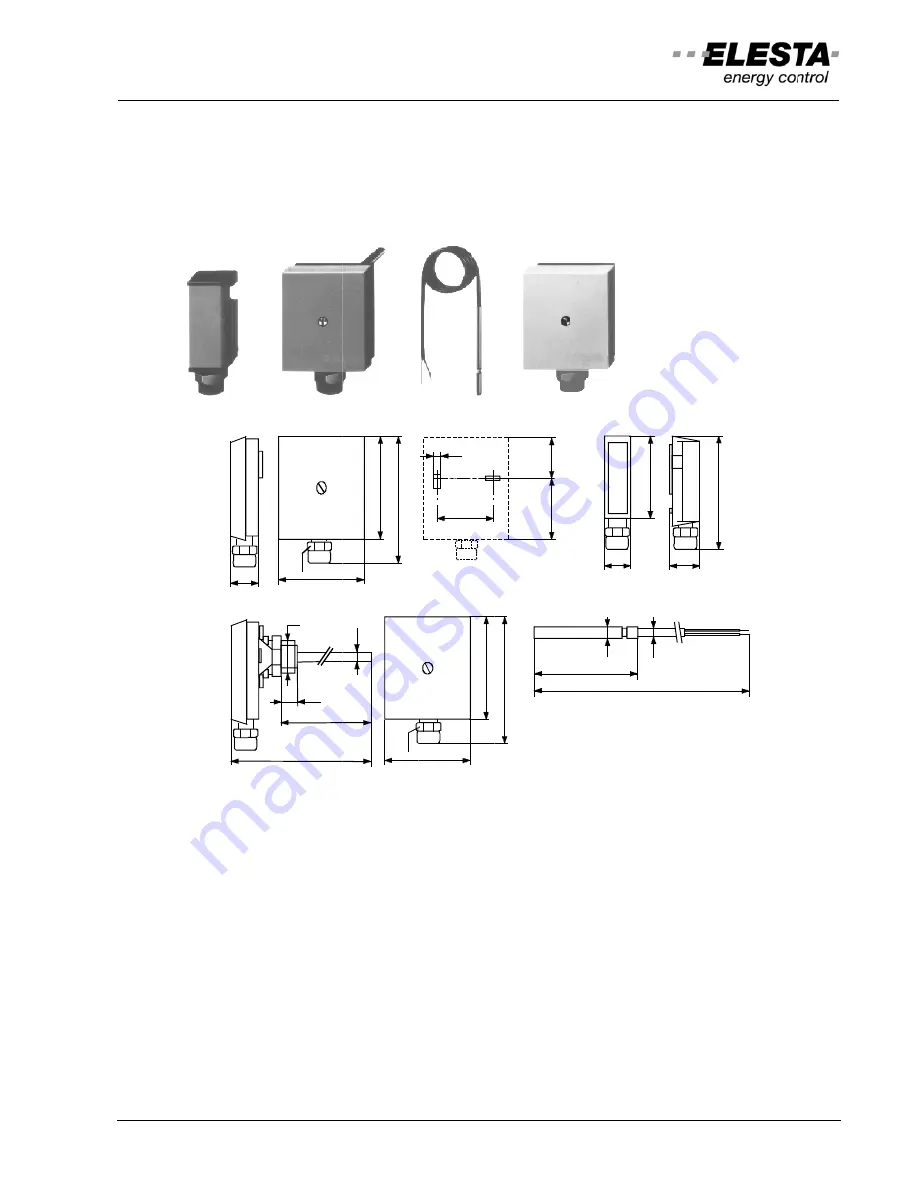
utdoor sens

ount at 2/3 o

orth-west sid

onnection 

rotection clas

lamp-on sen

ount in the fl
ixing valve. M

onnection 

rotection clas

mmersion se

ount in the fl
ixing valve. M

onnection 

rotective tube
rotection clas

28

mperature

e 2x1mm², un

of conduit- o

up to 
up to 
up to 

FT2A 

sor FT12A: 

of building he

e. 

: 2-wa

ss : 

IP40

nsor FT1A: 

low immedia
Mount with c

: 2-wa

ss : 

IP40

ensor FT2A:

low immedia
Mount in a p

: 2-wa

e : 

100m

ss : 

IP40

58

PG

9

142

100

13

G1/2"

RDO3x3A

e sensors

nshielded, se

or connector 

25m
50m

100m

eight, not abo

ay screw term

ately behind t

clamping ban

ay screw term

ately behind t

ipe bend poi

ay screw term

mm for PN10

68

86

PG

9

9

A


17

eparated from

boxes. 

Ca
Ca
Ca

RFT

(NTC 10k

Ω

ove window o

minal (cable 

Measuring

(PTC 1k

Ω

;

the pump or,

nd ZB126A o

minal (cable 

Measuring

(PTC 1k

Ω

;

the pump or,

nted towards

minal (cable 

Measuring

5

40

58

68

86

m mains lines

able cross se
able cross se
able cross se

FT1

RFT113B2
RFT203B4
RFT303A5

Ω

; by 25°C

)

or underneat

glands: PG9

 range 

; by 25°C) 

 if pump in re

on blank pipe

glands: PG9

 range  

; by 25°C) 

 if pump in re

s the flow. 

glands: PG9

 range 

46

22

86

s. Max. lengt

ection: 0.2
ection: 

0

ection: 1

12A 

20: L=2m
40: L=4m
50: L=5m

th roof protru

9) 

: -30..40°C 

eturn, approx

e, no thermal

9) 

: -30..120°C 

eturn, approx

9) 

: -30..120°C 

50

L

6

P

30

62

th for passive

25 mm

2


0.5 mm

2


.0 mm

2


usions, prefe

ximately 1.5m

 conductive 

ximately 1.5m

L

4,5

80

29

PG9

62

e sensors 10

FT1A 

RFT11
RFT20
RFT30

erably on nort

m behind the

paste neces

m behind the

00m. 

13B 
03B 
03A 

th or 

sary. 

Summary of Contents for DOMOTESTA RDO353A series

Page 1: ...User manual RDO3x3A 162515v44 11 10 Specifications are subject to change 1 User manual DOMOTESTA RDO353A V4 40 RDO383A V4 40 Weather or room temperature compensated heating controller ...

Page 2: ... settings 10 4 Installation 15 4 1 Controller 15 4 2 Sensors 16 4 3 Accessories 18 5 Terminal assignment 19 5 1 Terminal designation 20 5 2 Controller RDO353A 21 5 3 Controller RDO383A 21 5 4 Heating circuit module RZM510A004 22 5 5 Boiler cascade module RZM530A004 22 5 6 DHW module RZM515A004 23 5 7 Address an parameter setting 23 6 Checklists 26 6 1 Initial start up 26 6 2 Trouble shooting 26 7 ...

Page 3: ...utions with different functions RDO353A000 2 stage or modulating burner boiler circulating pump 1 mix heating circuit 3 point valve and pump DHW pump RDO383A000 2 stage or modulating burner boiler circulating pump 2 mix heating circuits 3 point valve and pump DHW pump This manual contains in its front section all necessary information for the user concerning operation and settings The installer fi...

Page 4: ...ot performed correctly may lead to faulty operations or destruction of the controller or system components Strictly observe the instructions supplied Note A Note indicates actions or procedures to avoid unexpected results or as tips for easier work They include extra information for the user 2 2 Correct usage The product accompanying this manual complies with the technical regulations valid at the...

Page 5: ...ted faulty parameter setting by non experts is prevented During regular undisturbed operation the basic indication on the LCD informs of operation mode errors or superimposed modes Pressing of any key will switch on the illumination Further operation is described below If there is no key pressed during a period of time the display falls back to basic indication and illumination is switched off The...

Page 6: ...ture Boiler temperature Water temperature DHW Room temperature Temperature setpoint indication Room Hot water Anti frost Anti frost Reduced Reduced Normal Normal flashing Anti legionella1 A Display field 1 B Display field 2 C Status indicator active outputs D Reference symbol heating circuit DHW circuit E Time switch program only ON segments are visible F Actual time G Active temperature setpoint ...

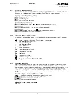
Page 7: ...1 Heat generator stage 2 Output PWM1 active Output PWM2 active Pump 1 direct heating circuit Pump 2 DHW charging Solar pump Pump MK mix circuit Symbol for mixing valve Mixing valve commands CLOSE OPEN 3 2 3 Indication of errors When an error occurs it will be recorded on the internal error list and indicated by the flashing display fields 1 and 2 It will only be shown this way on the basic indicat...

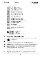
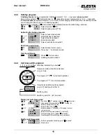
Page 8: ...ction Er 6x Device bus conflicts during installation or operation Er 7x Field bus errors during installation or operation Er 8x Interface errors Erase error memory Select field 90 YYXX Select parameter 90 90 YYXX Press for 5 seconds S Er Error memory erased 90 0 Error memory is not accessible if empty 3 3 Operation level l Simple operation settings 3 3 1 Mode switch 1 for boiler cascades When the ...

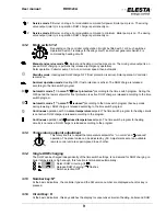
Page 9: ...ost protection is active DHW charge is released according to the time switch program Automatic mode normal reduced according to the time switch program back up mode during lowering DHW charge is released according to the time switch program Continuous operation with normal temperature setpoint The time switch program for heating circuits is not active DHW charge is released according to the progra...

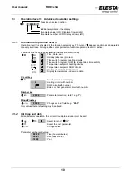
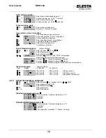
Page 10: ...me switch program Heating circuits Time switch program DHW independent time switch Temperature setpoints heating circuits Temperature setpoints DHW circuits Heating characteristic adjustment Display temperatures and service data Circuit key K Circuit selection and display 2 Heating circuit with number 2 DHW circuit with number 3 Boiler or heat generator circuit with number Number key 1 20 30 Param...

Page 11: ...02 Select date of return even 1 Press key until block erased Clearing all blocks 1 29 01 Press for 5 seconds 1 Holiday programs erased 3 4 4 Set time switch program Weekday indicated by cursor Operation mode at the time indicated e g normal Time segment for reduced operation Time segment for normal operation Circuit selected time switch program e g 2 heating circuit No 2 Switching time Switching p...

Page 12: ...s key for 5 seconds COPY is displayed After 5 seconds one of the following appear S UH 2 Function Standard program 2 loaded S Ub 2 Function Standard program 2 loaded S UF 9 Function Standard program independent time switch loaded Standard program factory settings Field Display 1 5 MO FR 6 7 SA SU 2 7 00 23 00 8 00 23 00 HK time switch 2 6 30 20 00 7 30 21 00 DHW time switch 9 6 30 20 00 7 30 21 00...

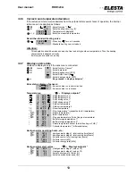
Page 13: ...x is short circuited xx C Sensor number xx is broken Temperatures Displays setpoint 1 55 C DHW temperature 1 2 53 C DHW temperature 2 3 58 C DHW mixing valve 1 4 65 C DHW mixing valve 2 10 5 C Outdoor temperature 11 5 C Outdoor temperature 2 12 20 1 C Room temperature 14 52 C Flow temperature respective boiler temperature 20 45 C Return temperature 21 60 C Boiler temperature 23 95 C Flue gas tempe...

Page 14: ...troller LMU64 1 4 YY 31 34 DHW circuits 1 4 XX Number of the error code XXX for LMU64 error codes 99 YYXX Earliest error entry Clearing error list 90 YYXX Press key for ca 5 seconds S Er Error list being cleared 90 0 Error list empty 3 4 8 Floor dry up program A2 0 C Select parameter A2 A2 50 C Set the maximal heat up temperature A2 x Press key for ca 5 seconds Sequence 6 Days Flow setpoint contin...

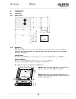
Page 15: ...511A Wall mounting Mount base plate RZB520A and wire it Plug device on and fix it RDO383A requires RZB511A DIN rail mounting Screw rail clamps RZB106A for DIN rail 35mm onto base plate RZB520A Snap base plate onto DIN rail and wire it Plug device on and fix it Base plate and extension of terminal compartment RZB520A Base plate with 2 side walls for glands 4xPG9 with screw able connectors RZB510A i...

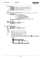
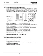
Page 16: ...perature setpoint adjustment status display LED Remote control unit RFB520A active connected to device bus Remote control unit with temperature sensor Program selection by single key temperature setpoint adjustment status display LED Comfort remote control RFB540A active connected to device bus Remote control unit with temperature sensor Program selection LCD indication Room temperature sensor RFT...

Page 17: ...ay screw term 0 ately behind t ipe bend poi ay screw term mm for PN10 0 68 86 PG9 9 A 17 eparated from boxes Ca Ca Ca RFT NTC 10kΩ ove window o minal cable Measuring PTC 1kΩ the pump or nd ZB126A o minal cable Measuring PTC 1kΩ the pump or nted towards minal cable 0 Measuring 5 40 58 68 86 m mains lines able cross se able cross se able cross se FT1 RFT113B2 RFT203B4 RFT303A5 Ω by 25 C or underneat...

Page 18: ...terface converter cable connecting controller to a PC RS232 Interface converter cable RZB010A Interface converter cable connecting controller to a PC USB 2 0 I O module disturbance module RZB540A Connection of up to four digital input signals 230VAC to one analog input for PTC or NTC at the RDO Offers one additional relay output controlled by a PWM output of RDO Wire cross section to RDO up to 15m...

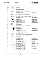
Page 19: ...diagram Observe local regulations regarding authorised personal Terminals 1 to 15 are for mains voltage 230 V The prints and relay contacts are not short circuit proof Operation tests of external loads must be carried out with unplugged controller In case of high inductive loads consumers contactors solenoid valves etc need parallel RC modules e g RIFA RC module 250VAC 0 1uF X2 47ohm Terminals 21 ...

Page 20: ...ct heating with HE for DHW Increase temperature 41 Q1 MK2 Mixing valve 2 CLOSE Command colder District heating with HE for DHW Decrease temperature B Low voltage Inputs and outputs 21 D Bus Device bus remote control units auxiliary modules and additional devices 22 D Bus Pole reversible connection 23 PWM2 Relay module or PWM output PWM pulse width modulation 24 PWM1 Relay module or PWM output Sola...

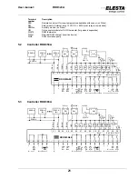
Page 21: ... 28 29 3 0 31 32 33 34 35 10 11 12 13 14 15 1 2 3 4 5 6 7 8 9 S1 RDO353A00 0 1 GND Ext 3 S2 0 1 Ext 2 Ext 1 S3 0 1 PWM1 PWM2 Ext 5 Bv Bk Ba Brü Br Bww Bag Bres 11 12 RM A1 A2 RZM5 A RFB5 A Br RFB5 A Br 11 12 RM A1 A2 WW el WWZ D Bus D Bus 2 3 OM 1 4 230VAC WW Th T S5 0 1 RZM5 A 5 3 Controller RDO383A L L MK2 MK2 N N L L L L on off Bh1 Bh2 HK MK1 MK1 N on WW N N N 21 22 23 24 25 26 27 28 29 3 0 31 ...

Page 22: ...530A004 S1 Aux input Boiler on standby 1 Boiler OFF frost protection active S2 Aux input Boiler temperature setpoint 1 Min temperature setpoint active Master controller device bus D Bus 2 wires invertible 1 2 3 4 5 6 7 8 9 21 22 23 24 25 26 27 28 29 3 0 31 32 33 34 35 L L N MK MK N RFB Br S1 RZM510A004 10 11 12 13 14 15 0 1 Bv Ba GND S2 0 1 Ext 2 Ext 1 Br S1 0 1 Bk GND Brü S2 0 1 Bag PWM 0 10V 1 2...

Page 23: ...g heating curve 1 Boiler cascade only Output for mixing valve 1 10 11 is used for the shut off valve 11 OPEN Mix circuit pump 1 9 is used as the common boiler pump Single boiler or weather compensated heating Nr 1 2 3 7 Par 110 0 KK Par 110 1 1 Par 110 2 KK 1 Par 110 3 KK 1 Par 110 4 1 2 Address RZM510A 2 3 7 Internally controlled heating circuits Boiler cascade or fixed value controlled heating T...

Page 24: ... the DHW modules RZM515A according their circuit number DHW circuit 1 is controlled by the RDO3x3A Same address numbers of heating circuits 1 7 or cascade circuits 1 4 do not interfere with DHW address numbers Address setting examples Boiler cascade 2 boilers 1 boiler 2 heating circuits 3 heating circuits Boiler cascade 2 boilers 2 heating circuits 2 DHW circuits Addr 2 RFB5x0A RFB510 3 3 MK 1 MK ...

Page 25: ...sed Boiler temp sensor 28 on the secondary side of heat exchanger Note District heating with two HE Additionally to the above for DHW Mixing valve 2 41 42 primary valve 42 ON increase return temp Reserved sensor 31 return of primary side of heat exchanger Note Gas boiler controller Stage 1 14 not used Stage 2 6 7 may be used for special applications Connect boiler return and flue gas sensor to gas...

Page 26: ...t level II Check the system s functioning at the different operation modes Set preferred operating mode Auto or Auto normal reduced or Auto normal frost protection Set time switch programs and the room temperature setpoints as desired see 3 4 4 and 3 4 5 Operation level II For boiler cascade and fixed temperature control set required boiler temperature setpoint at basic indication by pressing keys...

Page 27: ...rgency operation for boiler cascades If heat generator and pump are still working set the mode switch to manual operation 1 for low to medium resp 2 for high energy demand Adapt boiler thermostat setting to the required flow temperature Open the mixing valve by hand as necessary For DHW charging set boiler temperature at least 10 C higher than DHW temperature setpoint Emergency operation for distr...

Page 28: ... basic indication Press key Presentation and meaning of parameters Parameter number Please note your individual settings here Circuit or here for more than one circuit Par 000 Parameter designation K 1 2 0 99 0 Description 1 9 Description 2 Value range From the parameters described herein only the ones relevant for your particular setting may be shown on your device Whether a parameter is accessib...

Page 29: ...boiler at defined partial load Par 109 2 As 1 for mixed boilers highest setpoint for all released boilers without Par 10h Par 107 Cascade release sequence 0 Regular sequence 1 Reverse sequence by auxiliary input terminal 35 31 2 Operating hours balance difference of over 100h Par 108 2nd source switching point Note Affected by Par 10d 0 Not used independent release of next step 1 Release both heat...

Page 30: ... 2 sensors at buffer storage 2 Pump to DHW boiler requires 2 sensors at buffer storage 4 Pump to DHW boiler then to buffer storage requires 2 sensors at buffer storage 11 Autonomous ΔT control no buffer storage necessary Par 10L Output solar diverting valve Parameter list as Par 10E 0 Without solar diverting valve Par 10n Energy release at flow temperature difference setpoint actual value 0 Inacti...

Page 31: ...mary side DHW charging pump secondary side 15 DHW charging pump primary side mix heating circuit secondary side 16 2 mix heating circuits MK pumps on the same output 17 Mix heating circuit to HE secondary side to circulation pump 21 As 11 but before buffer storage circuits 2 4 only 22 As 12 but before buffer storage circuits 2 4 only 23 As 13 but before buffer storage 24 As 14 but before buffer st...

Page 32: ...ol mix circuit 1 7 10 50 Maximum setpoint for swimming pool control Par 11F DHW circuit energy demand K 1 2 3 4 0 Energy demand to heat generator 1 7 Energy demand to pre control mix circuit 1 7 11 No energy demand to heat generator Configuration of electrical inputs and outputs Warning Low voltage inputs Par 120 Auxiliary input 1 terminal 35 0 No function 1 Set system to standby 2 Set summer oper...

Page 33: ...ance 35 inverted NC 181 Ext disturbance 36 182 Ext disturbance 37 183 Ext disturbance 38 184 Ext disturbance 39 191 Ext disturbance 32 192 Ext disturbance 33 193 Ext disturbance 34 194 Ext disturbance 35 Par 121 Auxiliary input 2 terminal 34 Parameter list as Par 120 following 18 Pulse input for counter 2 terminal 34 only 120 Ext disturbance 36 39 inverted NC I O module 2 x E1 distr 36 E4 distr 39...

Page 34: ...ch channel 9 0 No output 1 External relay PWM1 terminal 24 ext relay 2 External relay PWM2 terminal 23 ext relay 3 DHW pump terminal 15 4 Boiler circuit pump terminal 8 5 Mix circuit pump 1 terminal 9 6 Mixing valve 1 ON terminal 10 7 Mixing valve 1 OFF terminal 11 8 Mix circuit pump 2 terminal 44 9 Mixing valve 2 ON terminal 42 10 Mixing valve 2 OFF terminal 41 11 Burner 1 terminal 13 12 Burner 2...

Page 35: ...t 54 DHW temperature mixing valve 2 setpoint 60 Building specific outdoor temperature Tageb 62 Room temperature setpoint 64 Flow temperature setpoint 70 Return temperature setpoint 71 Heat generator temperature setpoint boiler 74 Buffer storage temperature 1 top setpoint 75 Buffer storage temperature 2 bottom setpoint 77 Return temperature HE primary side for DHW charge setpoint 78 Temperature dif...

Page 36: ...on mode setting for DHW K 1 2 3 4 Note Function as corresponding mode switch 1 7 1 OFF 2 standby 3 DHW continuously released 4 auto 5 50 setpoint 6 55 setpoint 7 60 setpoint Par 13E Meter factor 1 0 01 0 99 99 Factor used on counter 1 Par 13F Meter factor 2 0 01 0 99 99 Factor used on counter 2 Configuration of heat generator and district heating Par 140 Switching difference SD1 K K 1 2 3 4 2 20 S...

Page 37: ...rive K Note Threshold at which continuous CLOSE command is given 10 40 P Band terminals for stage 2 OPEN CLOSE Par 14E District heating transition time of valve drive 0 5min 0 5 5 Transition time of valve drive Par 14F Allowed number of heat generator starts per hour 0 OFF 1 20 Allowed number of heat generator starts per hour delay between subsequent starts is 60 min 1 20 District heating Par 14h ...

Page 38: ...ion K 1 2 3 4 0 Both OFF 1 Boiler start up relief and DHW discharge protection ON 2 Boiler start up relief only 3 DHW discharge protection only 11 As 1 with rise Tkmin 12 As 2 with rise Tkmin Par 158 Alternate boiler minimum temperature setpoint Tkmin_ext C 0 OFF 1 125 Alternate boiler minimum temperature setpoint activated via auxiliary input Par 159 Alternate minimum flow temperature setpoint Tv...

Page 39: ...Flow temperature at the design point Par 163 Auxiliary boiler temperature at fixed point Tkausl C Note Set Par 110 2 20 99 Boiler temperature at the design point at Taausl Par 164 Adapted flow temperature at fixed point read only C K 1 2 3 4 5 6 7 10 40 Adapted flow temperature at the fixed point Ta 20 C Par 165 Adapted flow temperature at design point read only C K 1 2 3 4 5 6 7 0 99 Adapted flow...

Page 40: ...l 0 75 K 1 Normal Radiator heating only Trsoll 0 25 K Par 172 Optimization of heating circuit switching times K 1 2 3 4 5 6 7 Note Switching times see Par 173 Par 174 0 OFF Begin and end of heating period according heating circuit time switch program 1 ON Begin and end of heating period advanced to heating circuit time switch program 2 Ramp function for begin of heating defined by parameter 173 Pa...

Page 41: ...he heating circuit pump Par 187 Frost protection temperature C 15 3 Controls pump frost protection room temperature sensor required Par 188 Follow up time of boiler circuit pump min K 1 2 3 4 0 180 Follow up time of the boiler circuit pump Par 18c Internal function of independent time switch channel 9 Parameter list as Par 12c Functions of frost protection Pump frost protection Heating circuit pum...

Page 42: ...is required Ext WWel requires signal on auxiliary input as Par 12x 0 Ext WWel active 1 Ext WWel active DHW pump ON if WWel ON 2 Ext WWel active and controller on summer operation mode 3 Ext WWel active or controller on summer operation mode 10 Buffer storage temperature too low 11 Buffer storage temperature too low and summer operation mode on 12 Buffer storage temperature too low related to DHW t...

Page 43: ...ence to Par 1A1 3K 0 16 Temperature difference at solar collector that shuts pump off TKOLDIFF Par 1A2 Par 1A3 Reaction on exceeding maximum collector temperature 0 None 1 Collector pump to max speed charge buffer storage 2 Terminate charge steam in collector Par 1A4 Maximum collector temperature C 0 240 Maximum collector temperature switching difference 20 Par 1A5 Reaction on exceeding maximum bu...

Page 44: ...ch minimum PWM signal strength is given Par 1b5 Temperature at maximum PWM signal strength C 125 125 Temperature up to which maximum PWM signal strength is given District heating with 2nd HE for DHW charging Par 1d9 District heating HE2 bend point 1 Ta C 0 30 Outdoor temperature at bend point 1 Par 1dA District heating HE2 return temperature 1 C 20 90 Return temperature at bend point 1 Par 1db Dis...

Page 45: ...ontrol functions are terminated Some of the functions or components can not be activated at the same time if the same relay is involved and the contactors are blocked against each other Such functions are marked with bars K Select circuit Parameter is available for every heat generator Parameter is available for every heating circuit Parameter is available for every DHW circuit Outputs that are no...

Page 46: ...ff on 84 15 DHW pump off on off on WWZ 85 10 DHW mixer pump off on off on off on Auxiliary inputs They re indicated by the weekday cursors as long as they re active connected to GND Weekday 1 2 3 4 5 6 7 active Terminal 35 34 33 32 31 3 4 Designation Ext 1 Ext 2 Bag Bww Bres Bh1 Bh2 Function digital Ext 1 Ext 2 Ext 3 WW Th Ext 5 Bh1 Bh2 52 digital inputs Ext 2 1 Ext 2 2 Ext 2 3 Ext 2 4 59 digital ...

Page 47: ...rol unit with or without room temperature sensor RM Relay module external relay connected to output PWM RZM510A Heating circuit module connected to D bus RZM530A Boiler cascade module connected to D bus S Slope standardized fixed point of heating characteristics S_akt Actual slope SD Switching difference SD1 SD2 Switching difference stage 1 Stage 2 SDWW Switching difference DHW standby Main functi...

Page 48: ...at generator 1 Plant hydraulics Date Name Boiler cascade module 2 Type RZM530A SW Version Plant hydraulics Function aux input 1 2 Function input Bh 1 2 Date Name Boiler cascade module 3 Type RZM530A SW Version Plant hydraulics Function aux input 1 2 Function input Bh 1 2 Date Name Boiler cascade module 4 Type RZM530A SW Version Plant hydraulics Function aux input 1 2 Function input Bh 1 2 Date Nam...

Page 49: ...nput 1 2 WW Th WWel Weekday on off on off on off Monday Tuesday Wednesday Thursday Friday Saturday Sunday DHW circuit 3 Type RZM515A symbol 3 lit DHW setpoint leg Plant hydraulics Aux input 1 2 WW Th WWel Weekday on off on off on off Monday Tuesday Wednesday Thursday Friday Saturday Sunday DHW circuit 4 Type RZM515A symbol 4 lit DHW setpoint leg Plant hydraulics Aux input 1 2 WW Th WWel Weekday on...

Page 50: ...ay on off on off on off Monday Tuesday Wednesday Thursday Friday Saturday Sunday Heating circuit 2 symbol 2 lit Room setpoint Remote control unit Plant hydraulics Aux input 1 2 Weekday on off on off on off Monday Tuesday Wednesday Thursday Friday Saturday Sunday Heating circuit 3 symbol 3 lit Room setpoint Remote control unit Plant hydraulics Aux input 1 2 Weekday on off on off on off Monday Tuesd...

Page 51: ...t hydraulics Aux input 1 2 Weekday on off on off on off Monday Tuesday Wednesday Thursday Friday Saturday Sunday Heating circuit 6 symbol 6 lit Room setpoint Remote control unit Plant hydraulics Aux input 1 2 Weekday on off on off on off Monday Tuesday Wednesday Thursday Friday Saturday Sunday Heating circuit 7 symbol 7 lit Room setpoint Remote control unit Plant hydraulics Aux input 1 2 Weekday o...

Page 52: ...User manual RDO3x3A 52 Your representation Your installer ...

Reviews: