User manual:
RDO3x3A
29
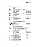
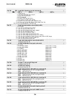
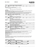
2 Heat generator dual stage
3 Modulating heat generator (burner)
10 Gas module for burner
11 Gas module for burner and RZM530A (special)
21 Heat pump single stage
22 Heat pump dual stage
Par 103
Flue gas temperature sensor
K
1:
2:
3:
4:
0 Without flue gas temperature sensor
1 With flue gas temperature sensor
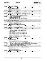
Par 104
Cascade type
Note:
For weather comp. control with fixed value base, the heating curve of virtual heating circuit
1 is used with Par.104=0 as boiler heating curve
0 Weather compensated (without common return control)
1 Fixed-value control (without common return control)
2 As 1 with common return control
10 As 0, boiler activation thru Tv1
11 As 1, boiler activation thru Tv1
Note:
Par.113 defines transition time of boiler circuit mixing valve.
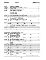
Par 105
Transition time of valve at boiler cascade circuit
K
1:
2:
3:
4:
0
Shut-off
valve
used
Note: The
mixing valve output CLOSE at the boiler cascade module RZM530A must be wired to
OPEN the shut-off valve
1..5
Transition time of mixing valve in minutes
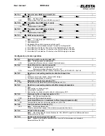
Par 106
Cascade strategy
0 Release next boiler at 100% power
1 Release next boiler at defined partial load (Par.109)
2 As 1 for mixed boilers (highest setpoint for all released boilers, without Par.10h)
Par 107
Cascade release sequence
0
Regular
sequence
1 Reverse sequence by auxiliary input (terminal 35..31)
2 Operating hours balance (difference of over 100h)
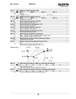
Par 108
2
nd
source switching point
Note:
Affected by Par.10d
0 Not used (independent release of next step)
1 Release both heat sources simultaneously
11 Change release sequence on every start
21 Swap active heat source (exclusive operation)
22 Swap active heat source, heat pump lock
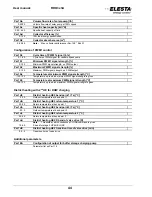
Par 109
Partial load switching point for next boiler [%]
K
1:
2:
3:
4:
0..100
Partial load switching point of individual max. load
Par 10A
Wait time to next stage [min]
K
1:
2:
3:
4:
1..60
Wait time before commencing next stage
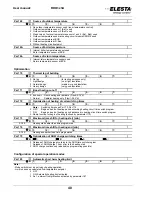
Par 10b
Boiler standby time [min]
K
1:
2:
3:
4:
1..120
Boiler on standby, KK pump on. Wait time (Par.10A not active)
Par 10c
2
nd
source switching point for cascade release [°C]
K
1:
2:
3:
4:
20
2
nd
source switching point inactive. The next step is on standby.
-20..20
Outdoor temperature for the release of the next step
Par 10d
2
nd
source switching point 2 [°C]
-40..60
5 Outdoor temperature for the release of 2
nd
step
Par 10E
Output boiler bypass pump
0
No
output
1 External relay PWM1
(terminal 24; ext. relay)
2 External relay PWM2
(terminal 23; ext. relay)

