User manual:
RDO3x3A
31
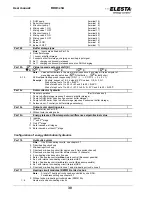
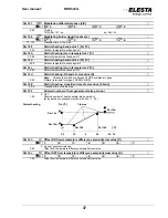
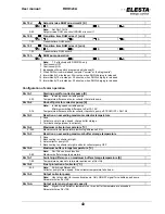
Par 112
Mixing valve drive (characteristic)
K
1: 2: 3: 4: 5: 6: 7:
2 2-point mixing valve drive is used (relay mixing valve_OPEN)
3 3-point mixing valve drive is used
Par 113
Transition time of the mixing valve [min]
K
1: 2: 3: 4: 5: 6: 7:
1..30
Transition time of the mixing valve drive (effective for 3-point action)
Par 114
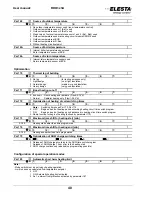
Heating circuit pump 1
0
Standard
ON/OFF
1 Speed control on 2 stages (external relay connected to terminal 24)
Par 115
Heating circuit pump 2
0
Standard
ON/OFF
1 Speed control on 2 stages (external relay connected to terminal 23)
Par 116
DHW hydraulics
K
1:
2:
3:
4:
* #
Note:
* available for RDO; # available for RZM515A
*
0 No DHW circuit
*
1 1 charging pump (at heat generator/storage)
*
2 Diverting valve (after boiler circuit pump)
*
3 With charging pump from distributor (KK-pump before distributor)
*
4 DHW charging by district heating (2
nd
HE)
*
5 Charging pump before buffer storage
*
6 Diverting valve before buffer storage
*
7 DHW electrical only
*
8 DHW combi storage
#
11 1 charging pump (at heat generator/storage)
#
12 2 pumps, external HE
*
#
13 Mix-heating circuit to DHW boiler
*
#
14 Mix-heating circuit primary side, DHW charging pump secondary side
#
15 DHW charging pump primary side, mix-heating circuit secondary side
#
16 2 mix-heating circuits, MK-pumps on the same output
* #
17 Mix-heating circuit to HE, secondary side to circulation pump
#
21 As 11, but before buffer storage (circuits 2..4 only)
#
22 As 12, but before buffer storage (circuits 2..4 only)
* #
23 As 13, but before buffer storage
* #
24 As 14, but before buffer storage
#
25 As 15, but before buffer storage (circuits 2..4 only)
#
26 As 16, but before buffer storage (circuits 2..4 only)
* #
27 As 17, but before buffer storage
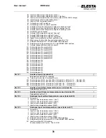
Par 117
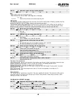
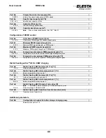
Equipment of the DHW storage
K
1:
2:
3:
4:
0 Thermostat connected to input Bww
1 Sensor connected to input Bww
2 2 sensors connected, layer storage charge (Bww, auxiliary input, max. limit by par.194)
3 As 2, but end of DHW charging by the lower temperature sensor (max. limit by par.194)
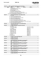
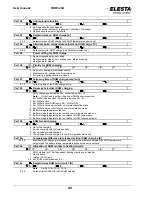
Par 118
Output electrical DHW heater
0
No
output
1
External relay PWM1
(terminal 24; ext. relay)
2 External relay PWM2
(terminal 23; ext. relay)
3
DHW
pump
(terminal
15)
4 Boiler circuit pump
(terminal 8)
5 Mix circuit pump 1
(terminal 9)
6 Mixing valve 1 ON
(terminal 10)
7 Mixing valve 1 OFF
(terminal 11)
8 Mix circuit pump 2
(terminal 44)
9 Mixing valve 2 ON
(terminal 42)
10 Mixing valve 2 OFF
(terminal 41)
11
Burner
1
(terminal
13)
12 Burner 2 ON
(terminal 6)
13 Burner 2 OFF
(terminal 7)


