User manual:
RDO3x3A
32
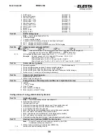
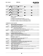
Par 119
DHW modules (RZM515A) at device-bus
Note:
A total of 3 DHW circuits can be controlled by one RDO
For address setting see chapter 5.7
0..3
Number of external DHW modules (RZM515)
Par 11A
Boiler circuit pump output (terminal 8) KK
0
Controlled
by
demand
1 Operate as buffer storage pump
2 Operate as buffer storage pump, deactivated for DHW charging
3 Free for other functions
4 Boiler circuit pump only if external minimal boiler setpoint activated (Par.12x=5 and Par.158=xx)
Par 11b
PWM1 output (terminal 24)
K
1:
2:
3:
4:
0
ON/OFF
1 PWM speed control for solar collector pump (needs Par.1bx)
3 Power control 0-10V for modulating heat generator (Par.1b1 and 1b2)
4 Boiler setpoint control 0-10V for modulating heat generator (based on par.1b4 and 1b5)
5 As 4, but with release by relay Br1
11 0..10V speed control for solar collector pump (needs Par.1bx)
101 Condensator pump (ON/OFF)
Par 11d
Autonomic return temperature regulation
0
Inactive
1 Relay mixing valve 1 OPEN/CLOSE (terminal 10/11)
2 Relay mixing valve 2 OPEN/CLOSE (terminal 42/41)
3 Relay burner 2 OPEN/CLOSE (terminal 6/7)
Par 11E
Heating circuit special function
K
1: 2: 3: 4: 5: 6: 7:
0
Not
used
1..7
Energy demand to pre-control (mix-circuit 1..7)
10..50
Maximum setpoint for swimming pool control
Par 11F
DHW circuit energy demand
K
1:
2:
3:
4:
0 Energy demand to heat generator
1..7
Energy demand to pre-control (mix-circuit 1..7)
11 No energy demand to heat generator
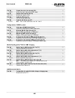
Configuration of electrical inputs and outputs
Warning: Low voltage inputs!
Par 120
Auxiliary input 1 (terminal 35)
0
No
function
1 Set system to standby
2 Set summer operation to all heating circuits
3 Release electrical DHW-charge
4 Operate on parameters for solid fuel
5 Activate minimum boiler temperature setpoint
6 Activate minimum flow temperature setpoint
7 Activate normal room temperature setpoint on heating circuit 1
8 Activate reduced room temperature setpoint on heating circuit 1
9 Signal: burner deactivated (no error signal)
10
Reverse
boiler
cascade sequence
11 Signal: Burner malfunction
12 Activate minimum buffer storage temperature setpoint
13
Activate
2
nd
source switching point 2 (Par.10d)
14 Force single DHW-charge (signal > 5 seconds)
15 Set heating circuit 1 to standby
16 Set heating circuit 1 to summer operation
17 Pulse input for counter 1 (terminal 35 only)
19 Operate on parameters for solid fuel without boiler circuit pump KK
20 Input for flue gas temperature sensor
21 Input for flow temperature sensor 2
22 Input for DHW temperature sensor 2 (bottom)
23 Input for flow temperature sensor 1
24 Input for return temperature sensor 1


