background image

SINUS-K


PROGRAMMING


MANUAL


131/

226


PARAMETERS OF THE MULTISPEED SUBMENU 


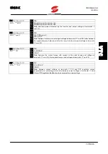
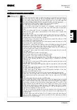
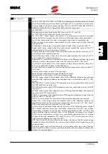
P39 Multispd 2/9 

P39 

ABS, ADD 

ABS 

MS func. = *** 

Determines the application of speed references obtained through par. P40÷P46. 

ABS – output speed matches with the speed reference output when parameters 

P40÷P46 are active. 

ADD – output speed matches with the sum of the main speed reference and the 

active speed reference. 


P40 Multispd 3/9 

P40 

–9000÷+9000 rpm 

speed1  ***rpm 

Determines the speed reference obtained when multifunction digital input 1 (terminal 

9) is active and set as multispeed (parameter C17, OP METHOD submenu). 


P41 Multispd 4/9 

P41 

–9000÷+9000 rpm 

speed2 = ***rpm 

Determines the speed reference obtained when multifunction digital input 2 (terminal 

10) is active and set as multispeed (parameter C18, OP METHOD submenu). 


P42 Multispd 5/9 

P42 

–9000÷+9000 rpm 

speed3 = ***rpm 

Determines the speed reference obtained when multifunction digital inputs 1 and 2 

(terminals 9 and 10) are active and set as multispeed (par. C17 and C18, OP 

METHOD submenu). 


P43 Multispd 6/9 

P43 

–9000÷+9000 rpm 

speed4 = ***rpm 

Determines the speed reference obtained when multifunction digital input 3 (terminal 

11) is active and set as multispeed (par. C19, OP METHOD submenu). 


P44 Multispd 7/9 

P44 

–9000÷+9000 rpm 

speed5 = ***rpm 

Determines the speed reference obtained when multifunction digital inputs 1 and 3 

(terminals 9 and 11) are active and set as multispeed (par. C17 and C19, OP 

METHOD submenu). 


V

T

C


Summary of Contents for SINUS CABINET K Series

Page 1: ...ational uses Elettronica Santerno is responsible for the device in its original setting Any changes to the structure or operating cycle of the device must be performed or authorized by the Engineering Department of Elettronica Santerno Elettronica Santerno assumes no responsibility for the consequences resulting by the use of non original spare parts Elettronica Santerno reserves the right to make...

Page 2: ...e SINUS K SINUS BOX K and SINUS CABINET K series with supply voltage ranging from 200Vac to 690Vac from Size S05 to Size S70 with IFD application software supply voltage ranging from 200Vac to 500Vac from Size S05 to Size S50 with VTC application software For LIFT software lift applications a separate Programming Manual is available ...

Page 3: ... 1 1 4 15 15 Loc Rem 14 1 1 4 16 Fire Mode IFD SW only 14 1 2 DIGITAL OUTPUTS 15 1 2 1 Open Collector Output 15 1 2 2 Relay Outputs 16 1 3 ANALOG INPUTS 17 1 3 1 Auxiliary analog input 17 1 4 ANALOG OUTPUTS FEATURES 18 1 4 1 Analog Outputs 18 2 MAIN REFERENCE 19 3 PROGRAMMABLE FUNCTIONS 24 3 1 VOLTAGE FREQUENCY PATTERN V F PATTERN IFD SW only 24 3 2 CARRIER FREQUENCY IFD SW only 26 3 3 SLIP COMPEN...

Page 4: ...nsation Submenu 109 6 3 10 D C Braking Submenu 110 6 3 11 Serial Network Submenu 112 6 4 CONFIGURATION TABLE FOR IFD SW PARAMETERS 114 7 LIST OF VTC SW PARAMETERS 115 7 1 MENU AND SUBMENU TREE STRUCTURE VTC SW 115 7 2 MEASURE PARAMETER MENU 117 7 2 1 Measure Menu 117 7 2 2 Key Parameter 120 7 2 3 Ramps Submenu 121 7 2 4 Reference Submenu 123 7 2 5 Output Monitor Submenu 126 7 2 6 Multispeed Submen...

Page 5: ...ead Only 196 10 5 SPECIAL PARAMETERS SWxx Read Only 198 10 6 SPECIAL PARAMETERS SPxx Write Only 198 11 PARAMETERS SENT VIA SERIAL LINK VTC SW 202 11 1 MEASURE PARAMETERS Mxx Read Only 202 11 2 PROGRAMMING PARAMETERS Pxx Read Write 203 11 2 1 Ramps Menu P0x P1x 203 11 2 2 Reference Menu P1x P2x 204 11 2 3 Output Monitor Menu P2x P3x 205 11 2 4 Multispeed Menu P3x P4x 206 11 2 5 Prohibit Speed Menu ...

Page 6: ...oltage of the inverter VDC LINK in case of mains failure with a higher a or shorter b duration than the motor stop time 36 Figure 16 Output frequency speed and DC braking current when the DC BRAKING AT STOP function is enabled 37 Figure 17 Output frequency speed and braking DC current when the DC BRAKING AT START function is active 38 Figure 18 Output frequency and braking direct current when the ...

Page 7: ...on the position of jumper J10 Auxiliary power supply 24 VDC terminal 15 is protected by a self resetting fuse Figure 1 Digital input control modes NOTE Terminal 14 CMD digital input zero volt is galvanically isolated from terminals 1 20 22 CMA control board zero volt and from terminal 25 MDOE emitter terminal of multifunction digital output Parameter M08 IFD SW or M11 VTC SW in the Measure submenu...

Page 8: ...ad see Section 5 1 COMMANDS MENU If the REV function reverse rotation is active the START input may be used only when the REV input is inactive if START and REV are enabled at a time the main reference is set to zero The Start input may be used along with MDI1 input configured as STOP with parameters C23 IFD SW or C17 VTC SW for a button control mode instead of a switch control mode 1 1 3 RESET TE...

Page 9: ...Var 1 Stop Fire Mode C17 Mlts1 Multispeed1 Mlts1 Up Stop Slave 10 MDI2 C24 Mltf2 Multifrequency 2 Mltf2 Down Var 2 Loc Rem Fire Mode C18 Mlts2 Multispeed2 Mlts2 Down Slave Loc Rem 11 MDI3 C25 Mltf3 Multifrequency 3 Mltf3 CW CCW V ar 3 DCB REV A M Lock Loc Rem C19 Mlts3 Multispeed3 Mlts3 CW CCW DCB REV A M Lock Slave Loc Rem 12 MDI4 C26 CW CCW Mltf4 Mltr1 DCB CW CCW REV A M Lock Loc Rem C20 CW CCW ...

Page 10: ...MDI3 X 0 0 0 0 1 1 1 1 0 0 0 0 1 1 1 1 MDI4 X 0 0 0 0 0 0 0 0 1 1 1 1 1 1 1 1 Active reference 0 P40 Freq1 P41 Freq2 P42 Freq3 P43 Freq4 P44 Freq5 P45 Freq6 P46 Freq7 P47 Freq8 P48 Freq9 P49 Freq10 P50 Freq11 P51 Freq12 P52 Freq13 P53 Freq14 P54 Freq15 VTC SW START 0 1 1 1 1 1 1 1 1 MDI1 X 0 1 0 1 0 1 0 1 MDI2 X 0 0 1 1 0 0 1 1 MDI3 X 0 0 0 0 1 1 1 1 Active reference 0 P40 Spd1 P41 Spd2 P42 Spd3 P...

Page 11: ...C20 or C21 VTC SW CW CCW Terminals 11 12 or 13 allow to reverse the motor direction of rotation for more details see section 3 9 DC CURRENT BRAKING To do so three steps are needed a a deceleration ramp to zero b the reversal of the motor direction of rotation c an acceleration ramp up to the preset speed 1 1 4 4 DCB DIRECT CURRENT BRAKING Terminals 11 12 13 C25 C26 C27 IFD SW or C19 C20 C21 VTC SW...

Page 12: ...ax preset frequency see parameters C07 and C13 fomax1 and fomax2 even if a higher frequency is required 1 1 4 7 V F2 SECOND VOLTAGE FREQUENCY PATTERN IFD SW ONLY Terminal 13 C27 V F2 One inverter can be used to control two motors having different ratings To do so two different parameter sets are to be programmed Each parameter set is selected with a digital command sent to terminal 13 Each motor w...

Page 13: ...or control C28 Ext IFD SW or C22 Ext VTC SW PID regulator used independently of the inverter operating mode PID regulator is disabled by enabling the A M command PID regulator output and internal integral term are forced to zero PID regulator no longer controls the external physical variable associated to its operation C28 Ref F Add F Add V IFD SW or C22 Ref Spd Add Spd VTC SW PID regulator used t...

Page 14: ...3 and 14 in the control board 3 Set MDI5 as auxiliary trip In that way the inverter will stop and indicate an auxiliary trip external alarm as soon as the motor temperature exceeds threshold value Tr 1 1 4 15 15 LOC REM Terminals 10 11 or 12 C24 C25 or C26 SW IFD otherwise C18 C19 or C20 VTC SW Loc Rem Enable the input programmed as Loc Rem This function allows to override parameters C21 C22 IFD S...

Page 15: ...requency speed threshold the transistor activates when the output frequency IFD SW or the motor speed VTC SW attains the level set through the Digital Output menu parameters P69 MDO level P70 MDO Hyst Figure 2 Connecting a relay to the OPEN COLLECTOR output The figure shows an example of a relay connected to the output CAUTION Always use freewheeling diode D for inductive loads e g relay coils CAU...

Page 16: ...OFF Factory setting is as follows RL1 relay ready terminals 26 27 and 28 energizes when the inverter is ready to supply the motor At power on the equipment takes some seconds before initializing the relay energizes when an alarm trips The alarm trip locks the inverter RL2 frequency speed threshold relay terminals 29 30 and 31 energizes when the output frequency IFD SW or the motor speed VTC SW att...

Page 17: ... P21 Aux Input Bias and P22 Aux Input Gain similarly to inputs relating to terminals 2 3 and 21 With reference to Fig 1 3 the programmable parameters are the following P21 Aux Input Bias value of the signal processed by the inverter expressed as a value percent when the signal applied to terminal 19 is equal to zero P22 Aux Input Gain amplification coefficient or weakening coefficient with which t...

Page 18: ...2 pos 1 2 pos 1 2 0 20mA pos 1 2 pos 2 3 pos 1 2 pos 2 3 X any position Through the OUTPUT MONITOR menu set the quantity for the analog output and the ratio between the value of the output signal and the measured quantity The ratio between the output signal and the measured quantity is expressed as the ratio between the quantity value and the relevant voltage value on the analog output e g Hz V fo...

Page 19: ...s as set parameter P15 Minimum Ref as The motor direction of rotation changes when the main reference sign becomes opposite Bipolar voltage 10V may be sent to input Inaux terminal 19 The motor direction of rotation changes when negative signals are sent Analog input Iref terminal 21 acknowledges a current value ranging from 0 to 20mA as an input signal factory setting 4 20 mA If parameters C22 IFD...

Page 20: ...W Frequency reference Fref expressed in Hz when the first V f pattern is active for factory setting see section 3 1 is calculated as follows Fref C07 100 P16 Vref 100 P17 C07 100 P19 Iref 100 P20 where Vref is the sum of the signals sent to terminals 2 and 3 expressed as a percentage with respect to 10V if the signal addition exceeds 10V still consider Vref 100 Iref is the signal sent to terminal ...

Page 21: ... result NOTE if P15 0 the frequency reference range is positive only 0 FOMAX the direction of rotation is not reversed by the command sent via keypad or through the UP DOWN command If negative values are set in parameters P40 P54 no frequency value is produced NOTE The direction of rotation is reversed only using the CW CCW command NOTE If a certain value is assigned to P15 e g 10 Hz the frequency...

Page 22: ...block Limit block Limit block Serial link Multifrequency Terminals Terminals 9 10 Terminal 9 10 11 Output frequency Ramps Terminals Terminals Terminals Limit block Pid regulation output Reference variation per cent Terminals Figure 5 Block diagram of main reference processing for IFD SW ...

Page 23: ...s Terminals Terminals Pid regulation output Terminals Terminals Limit Block Terminals Multispeed Limit block Limit block Limit block Limit block Allowable range Input signal processing block Figure 6 Block diagram of main reference processing for VTC SW ...

Page 24: ... operation fomax C07 C13 maximum output frequency produced by the inverter fomin C08 C14 minimum output frequency produced by the inverter always contact Elettronica Santerno before altering this value Vmot C09 C15 motor rated voltage corresponding to the rated value this is the voltage obtained at the motor rated frequency Boost C10 C16 determines the variation of the output voltage fmot 20 Boost...

Page 25: ...rogramming the V f pattern of a 400V 50Hz motor to be used up to 50Hz with the following parameters depending on application requirements C06 50 Hz C07 50 Hz C09 400 V C10 25 C11 5 C19 50 C20 60 the V f pattern effectively obtained is the following 0 50 100 150 200 250 300 350 400 450 0 10 20 30 40 50 60 Hz V straight line actual pattern NOTE Because decreasing voltages values could stall the moto...

Page 26: ...r C78 Rs Stator resistance of the connected motor 3 2 CARRIER FREQUENCY IFD SW only Carrier frequency may be programmed based on output frequency as shown in Fig 8 Adjust parameters in the Carrier Freq submenu Configuration menu C01 MIN CARRIER Minimum value of PWM modulation frequency C02 MAX CARRIER Maximum value of PWM modulation frequency C03 PULSE NUMBER Number of output pulses produced when ...

Page 27: ...equal to C02 A decreasing carrier frequency improves the motor performance at low rpm but implies a louder noise Because carrier frequency fC can never exceed 16000 Hz if a high output frequency is required set C03 12 to obtain synchronous modulation when maximum output frequency is attained The diagram shows an example of the carrier frequency recommended to obtain a maximum output frequency of 8...

Page 28: ...meter C55 is set to YES factory setting or to YES A When parameter C55 is set to YES do the following to enable speed searching open and close terminal 6 ENABLE before tSSdis is over see Fig 10 disable DC braking before the time set is over see section 3 9 3 reset an alarm trip with a reference other than 0 before tSSdis is over see Fig 12 Speed searching is not performed when voltage is removed f...

Page 29: ...SINUS K PROGRAMMING MANUAL 29 226 Figure 10 Output frequency and motor rpm during speed searching C55 YES or C55 YES A activated by the ENABLE command tOFF tSSdis C56 or C56 0 ...

Page 30: ...a value corresponding to 1 25xC66 during time t2 output frequency is decreased to perform speed searching Speed searching occurs when the output current drops below the value set in C66 during time t3 the motor attains its prior speed following the acceleration ramp Figure 11 Frequency rpm of the inverter motor during speed searching power off C55 YES A due to the adjustment of the ENABLE command ...

Page 31: ...12 Output frequency rpm inverter locked reset and ENABLE commands during speed searching due to an alarm trip C55 YES or C55 YES A tOFF tSSdis C56 or C56 0 If parameter C61 is set to YES it is not necessary to open and close the ENABLE command ...

Page 32: ...to an alarm reset and to voltage removal from the inverter C55 YES A t1 t2 tSSdis C56 or C56 0 If parameter C61 ENABLE is set to YES it is not necessary to open and close the ENABLE command after resetting the alarm or switching on the inverter when C53 is set to YES If parameter C53 PWR Reset is set to YES it is not necessary to use the RESET command ...

Page 33: ...d DOWN ramps that cannot be altered can activate the digital output if any set with parameters P60 P61 P62 ignores the following alarms o A11 Bypass Circuit Failure o A18 Fan Fault Overtemperature o A18 Second Sensor Overtemperature o A20 Inverter Overload o A21 Heatsink Overheated o A22 Motor Overheated o A25 Mains Loss o A36 External Failure o A40 Serial Communication Error activates an infinite...

Page 34: ...e ranging from 0 to three times the motor rated speed The operator should know the parameters of the asynchronous machine equivalent circuit in order to use sensorless vector control see Fig 14 l2 l1 Rs is Vs M RR S Figure 14 Equivalent circuit of the asynchronous machine Where RS Stator resistance wiring included RR Rotor resistance l1 l2 Full leakage inductance M Mutual inductance not required f...

Page 35: ...que equal to 15000 C 100 9 Nm 1420 2π 60 In that case the starting torque will be equal to rated torque 120 121 1 Nm 3 8 POWER DOWN In case of mains failure it is possible to keep the inverter running by exploiting the kinetic energy of the motor and load energy recovered during the motor slowing down is used to supply power to the inverter thus avoiding loosing control due to a mains black out Al...

Page 36: ...ed and DC bus voltage of the inverter VDC LINK in case of mains failure with a higher a or shorter b duration than the motor stop time NOTE IFD SW only At power down if the inverter stops due to Undervoltage alarm of the bus voltage because energy recovered for the inverter operation is not sufficient speed searching will occur only if this function is enabled C55 set to YES A and under the condit...

Page 37: ...AT STOP BRAKING AT POWER DOWN BELOW STOP SPEED NO NO NO YES YES NO YES A YES YES YES B NO YES DC braking at stop occurs when a ramped stop command is sent Depending on the preset control mode do the following to obtain DC braking at stop open terminal 7 connection when terminal board control mode is active or disable the REV command if used send a STOP command via keypad Fig 16 shows the output fr...

Page 38: ...ing at start can be obtained sending a START command terminal 7 via terminal board or through the terminal set as REV using one of the digital inputs programmed as multifrequency multispeed controlling the equipment run via keypad Figure 17 Output frequency speed and braking DC current when the DC BRAKING AT START function is active Use the following parameters to program this function C81 IFD SW ...

Page 39: ... braking is performed output frequency speed is produced based on the acceleration ramp b DC braking time is under tDC IFD SW b1 DC braking time is under disabling time tSSdis C56 see section Speed searching DC braking stops when terminal set as DCB opens the equipment generates the frequency output produced before the DC braking command was sent if the speed searching function is enabled Otherwis...

Page 40: ...nt conditions Use the following parameters to program this function C82 IFD SW or C72 VTC SW braking time period at STOP C84 IFD SW or C74 VTC SW initial braking frequency at STOP C85 IFD SW or C75 VTC SW braking current intensity C56 IFD SW only disabling time of the Speed Searching function t t a f n tDC b1 f tDC tDCB ON tDCB ON tDC d and tDCB ON tSSdis C56 t b2 f tDC tDCB ON ON OFF tDCB ON tDC ...

Page 41: ...also determines a rise in temperature thus avoiding condensation Fig 19 shows the output frequency and braking DC when this function is activated Holding direct current activates after the injection of direct current both via terminal board and through the DC braking at stop function Use the following parameters to program this function C86 function enabling C87 intensity of the holding direct cur...

Page 42: ...re T is the motor thermal time constant C72 IFD SW or C67 VTC SW Heating is proportional to the efficient current2 I0 2 Overheating alarm A22 trips if the current flowing in the motor determines a higher temperature than the allowable asymptotic value set with It C71 IFD SW or C66 VTC SW t K I 2 t T I It 02 01 I It 02 01 2 K I YES B 3 FMOT 0 5 FMOT NMOT YES YES A 0 8 It 0 6 It 0 3 0 5 f nMOT f nMO...

Page 43: ...ee prohibit frequency speed ranges may be programmed To do so set up intermediate values and a hysteresis common to all three ranges Set an intermediate value to zero to disable the relevant prohibit range The output frequency range varies until the new reference value is reached Figure0 21 Prohibit frequency speed ranges Use the following parameters to program this function P55 intermediate frequ...

Page 44: ...r with respect to the physical values it is controlling Add F Add R PID regulator output is summed to the main frequency speed reference the motor speed is adjusted by PID regulator Add V IFD SW only PID regulator output is used to adjust the inverter output voltage but not the inverter output frequency the inverter behaves as a frequency generator whose voltage is managed by PID regulator 3 12 2 ...

Page 45: ...ms proportional term P multiplying the difference between the reference value to be obtained from the physical quantity to adjust and the feedback value measured by the physical quantity That difference is called an error and is multiplied by a Kp constant P86 Prop Gain When Kp increases the incidence of the proportional term in the regulator output signal also increases regulator becomes more sen...

Page 46: ...PROGRAMMING SINUS K MANUAL 46 226 Figure 22 PID regulator block diagram common section ...

Page 47: ...SINUS K PROGRAMMING MANUAL 47 226 Figure 23 PID regulator block diagram relating to IFD SW only Figure 24 PID regulator block diagram relating to VTC SW only ...

Page 48: ...e press the HOME key to access directly to the first page of the submenu 4 1 MAIN MENUS Main menus are the following M P measure parameter relates to the values displayed and to the parameters that can be altered when the inverter is running Cfg configuration includes those parameters that cannot be altered when the inverter is running Cm commands includes the pages relating to the inverter operat...

Page 49: ...the access pages of the different submenus Press PROG Esc to return to the main menu Press PROG Esc from the first page of the Configuration menu to access another main menu e g Measure Parameter The display shows Press and to select M P and press PROG to access the M P menu PROG SAVE CONFIGURATION Esc Prv Nxt PROG SAVE INVERTER OK M P Cfg Cm Srv ...

Page 50: ...ore the new value press PROG to store the new value until the inverter is turned off To quit the submenu scroll the different parameters up to the first page of the submenu or press the HOME key press PROG to access the submenu level Example Programming parameter P05 acceleration time 1 Access the M P menu Measure Parameter the first page of the M P menu is displayed use Nxt and Prv to scroll the ...

Page 51: ... alter the parameter value Press and to increase or decrease the parameter value Press SAVE to store the new value to non volatile memory Press PROG to store the new value until the inverter is turned off At next power on the inverter will use the last value saved to non volatile memory ...

Page 52: ...splays the inverter operating variables Access page Press PROG Ent to access the Keypad submenu Press Nxt and Prv to scroll through the other submenus of the Commands menu First page Use parameter C63 IFD SW or C55 VTC SW to setup the variable displayed on the first line at power on The contents of the second line depend on the programming of parameters Start Operation Ref Operation and PID Ref C2...

Page 53: ...nu Press PROG or SAVE to display a different variable in the first line Press Dn and Up to decrease or increase PID regulator reference if RG is displayed 3 Start Operation Term Ref Operation KPD PID Ref KPD Inputs for the frequency main reference are disabled in the terminal board Press MENU to quit the submenu Press PROG or SAVE to display a different variable in the first line Press Dn and Up t...

Page 54: ...ameters of the MEAS PARAMETER menu and the CONFIGURATION menu to be automatically restored except for UP DOWN reference and PID reference sent from keypad Access page Press PROG Ent to access the submenu press Nxt and Prv to scroll through the other submenus of the Commands menu NOTE The Restore Default submenu can be accessed only if parameter P00 MEAS PARAMETERS Key parameter is set to 1 default...

Page 55: ...ther submenus of the Commands menus NOTE To access the submenu set parameter P00 MEAS PARAMETERS Key parameter to 1 default The inverter must not be in RUN mode First page Press PROG Esc to quit the Save User s Parameters submenu press SAVE for a few seconds to save all parameters Square brackets indicate that parameters are being saved to Eeprom when square brackets disappear after a few seconds ...

Page 56: ...g on thermoswitch N fan state reading control depending on NTC Field JJJJ Software installed IFD VTC LIFT not covered in this manual Field w www FLASH software version human interface Field z zzz Software DSP version motor control NOTE If software version w www for the human interface is incompatible with software version z zzz for the motor control even if they both relate to IFD or VTC alarm A01...

Page 57: ...m M14 3 rd alarm M15 4 th Alarm M16 5 th Alarm M17 Aux Input M18 PID Ref M19 PID F B M20 PID Err M21 PID Out M22 FEEDBACK PID REGULATOR REFVAR DIGITAL OUTPUT PROHIBIT FREQUENCIES MULTIFREQ PROG PROG PROG PROG PROG PID REGULATOR REFVAR DIGITAL OUTPUT PROHIBIT FREQUENCIES MULTIFREQ P85 Sampling Time P75 VAR 1 P60 MDO Operation P55 FP1 P38 Fire Mode Freq P86 Prop Gain P76 VAR 2 P61 RL1 Operation P56 ...

Page 58: ...TIONS AUTORESET LIMITS C74 Poles C70 Thermal Prot C54 Vmains Nom C51 AttemptsNumber C40 Acc Lim C75 Motor Power C71 Motor Current C55 Speed Search C52 Clear Fail Time C41 Acc Lim Curr C76 No Load Current C72 Thermal Const C56 S S Dis Time C53 PWR Reset C42 RUN Lim C77 Motor Slip C57 Brake Unit C43 RUN Lim Curr C78 Stator Res C58 Fan Force C44 Dec Lim C59 Reduction Ratio C45 Dec Lim Curr C60 Mains ...

Page 59: ...scroll the submenus All parameters are included in different submenus except for key parameter P01 and the parameters relating to the inverter ratings Scroll the submenus to directly access these parameters 6 2 1 MEASURE SUBMENU The Measure submenu contains the variables displayed when the inverter is running Access page Press PROG Ent to access the first page of the Measure submenu Press Nxt and ...

Page 60: ...3 P M05 R Depending on the inverter class Vmn V F Mains voltage value M06 D C link 7 23 P M06 R Depending on the inverter class Vdc V F Value of DC link voltage M07 OUT P 8 23 P M07 R Depending on the inverter size POUT kW F Value of active power delivered to the load M08 Term Brd 9 23 P M08 F Condition of digital inputs in the terminal board display order terminals 6 7 8 9 10 11 12 13 If an input...

Page 61: ...last alarm tripped and relevant M11 value M13 2nd al 14 23 P M13 R A01 A40 A h F Stores the last but one alarm tripped and relevant M11 value M14 3rd al 15 23 P M14 R A01 A40 A h F Stores the last but two alarm tripped and relevant M11 value M15 4th al 16 23 P M15 R A01 A40 A h F Stores the last but three alarm tripped and relevant M11 value M16 5th al 17 23 P M16 R A01 A40 A h F Stores the last b...

Page 62: ...D 1 P00 F 0 only parameter P00 may be altered 1 all parameters may be altered parameters included in the Configuration menu can be altered only if the inverter is disabled NOTE Parameter P00 can be saved if P00 0 is saved the alteration of the other parameters is inhibited at the following start up NOTE The parameters of the configuration menu Cxx can be altered only if the inverter is not in RUN ...

Page 63: ...11 P P07 R 0 6500s D 10s Tac2 s F Time interval of acceleration ramp 2 from 0 to FOMAX1 P08 Decel t 5 11 P P08 R 0 6500s D 10s Tdc2 s F Time interval of deceleration ramp 2 from FOMAX1 to 0 P09 Accel t 6 11 P P09 R 0 6500s D 10s Tac3 s F Time interval of acceleration ramp 3 from 0 to FOMAX1 P10 Decel t 7 11 P P10 R 0 6500s D 10s Tdc3 s F Time interval of deceleration ramp 3 from FOMAX1 to 0 P11 Ac...

Page 64: ... when accelerating and decelerating P14 Ramp 11 11 P P14 R 1 2 4 8 16 32 D 4 ext F Multiplicative factor of the active ramp in the time interval defined by parameter P13 NOTE The active ramp depends on the condition of inputs MDI4 and MDI5 whether they are programmed to alter ramp time periods see Operation method submenu parameters C26 and C27 NOTE Ramp time relates to FOMAX2 parameter C13 when t...

Page 65: ...CE SUBMENU P15 Minimum 2 13 P P15 R 0 800 Hz for S05 S30 R 0 120 Hz for S40 S70 D Freq Hz F Minimum value of the frequency reference Set to obtain a bipolar frequency reference range P16 Vref 3 13 P P16 R 400 400 D 0 Bias F Voltage percent value when no voltage is applied to terminals 2 and 3 P17 Vref 4 13 P P17 R 500 500 D 100 Gain F Proportional coefficient between the sum of signals on terminal...

Page 66: ...inal 21 P20 Iref 7 13 P P20 R 500 500 D 125 Gain F Proportional coefficient between the current reference sent to terminal 21 expressed as a fraction of the maximum allowable value 20mA and the reference obtained expressed as a percentage NOTE Factory setting of parameters P19 and P20 corresponds to 4 20mA current reference signal NOTE For any detail on how to use paramters P16 P17 P18 P19 P20 see...

Page 67: ...e command sent via keypad 0 Range 0 to FOMAX Range FOMAX to FOMAX P24 U D Mem 11 13 P P24 R NO YES D YES NO YES F If set to YES stores the increment or decrement of the frequency reference value sent either via terminal board through MDI1 and MDI2 and set as UP and DOWN see parameters C23 and C24 or via keypad see COMMAND menu P25 U D Res 12 13 P P25 R NO YES D NO NO YES F If set to YES allows to ...

Page 68: ...ut Pout Nout PID 0 PID F B D Fout Monitor 1 F Selects the quantity for the first multifunction analog output terminal 17 among Fref frequency reference Fout output reference lout output current Vout output voltage Pout output power Nout rpm PID 0 PID regulator output PID F B PID regulator feedback P31 Output 3 9 P P31 R Fref Fout Iout Vout Pout Nout PID 0 PID F B D Iout Monitor 2 F Selects the qua...

Page 69: ...18 P35 Out mon 7 9 P P35 R Depending on the inverter size D Depending on the inverter size KOP kW V F Ratio between power delivered by the inverter and output voltage at terminals 17 and 18 P36 Out mon 8 9 P P36 R 90 10000 rpm V D 200 rpm V KON rpm V F Ratio between motor RPM and output voltage at terminals 17 and 18 NOTE Motor RPM is given by Fout output frequency multiplied by constant 60 x 2 C5...

Page 70: ...U P38 FireMode 2 18 P P38 freq Hz R 800 800 Hz for S05 S30 R 120 120 Hz for S40 S70 D 25 Hz F Determines the frequency reference which is active in Fire Mode P39 Multif 3 18 P P39 R ABS ADD D ABS M F FUN F Determinestheapplicationoffrequencyreferencesobtainedthroughpar P40 P54 ABS output frequency matches with the frequency reference obtained when parameters P40 P45 are activated ADD output freque...

Page 71: ...or S05 S30 120 120 Hz for S40 S70 D 0 Hz freq5 Hz F Determines the frequency reference obtained when multifunction digital inputs 1 and 3 terminals 9 and 11 are active and set as multifrequency par C23 and C25 OP METHOD submenu P45 Multif 9 18 P P45 R 800 800 Hz for S05 S30 R 120 120 Hz for S40 S70 D 0 Hz freq6 Hz F Determines the frequency reference obtained when multifunction digital inputs 2 an...

Page 72: ...00 Hz for S05 S30 R 120 120 Hz for S40 S70 D 0 Hz freq12 Hz F Determines the frequency reference obtained when multifunction digital inputs 3 and 4 terminals 11 and 12 are active and set as multifrequency par C25 and C26 OP METHOD submenu P52 Multif 16 18 P P52 R 800 800 Hz for S05 S30 R 120 120 Hz for S40 S70 D 0 Hz freq13 Hz F Determines the frequency reference obtained when multifunction digita...

Page 73: ...alue is reached For more details see section 3 11 PROHIBIT FREQUENCY SPEED Access page Press PROG Ent to access the first page of the Prohibit Frequencies submenu Press Nxt and Prv to scroll through the submenus First page Press PROG Esc to return to the Prohibit Frequencies submenu access page Press Nxt and Prv to scroll through the parameters PROG SAVE Menu Prohibit f Ent Prv Nxt PROG SAVE Prohi...

Page 74: ...Hz Fp2 Hz F Determines the intermediate value for the second prohibit frequency range The intermediate value is an absolute value i e is not depending on the direction of rotation Set it to 0 to disable the prohibit frequency range P57 Prohib f 4 5 P P57 R 800 800 Hz for S05 S30 120 120 Hz for S40 S70 D 0 Hz Fp3 Hz F Determines the intermediate value for the third prohibit frequency range The inte...

Page 75: ...ts Access page Press PROG Ent to access the first page of the Digital Output submenu Press Nxt and Prv to scroll through the submenus First page Press PROG Esc to return to the Digital Output submenu access page Press Nxt and Prv to scroll through the parameters PROG SAVE Menu Digital Out Ent Prv Nxt PROG SAVE Dig output 1 16 Ent Prv Nxt IFD ...

Page 76: ... inverter is limited by the motor Generator lim active output limit during regeneration stage PID OK active output if the absolute value of the difference between the reference signal and PID regulator feedback has dropped below a threshold set with P69 MDO Level see Fig 6 5 PID OUT MAX active output if PID regulator output has reached the value set for P90 PID MAX Out see Fig 6 6 PID OUT MIN acti...

Page 77: ...ting stage Motor limiting active output the inverter is limited by the motor Generator lim active output limit during regeneration stage PID OK active output if the absolute value of the difference between the reference signal and PID regulator feedback has dropped below a threshold set with P71 RL1 Level see Fig 6 5 PID OUT MAX active output if PID regulator output has reached the value set for P...

Page 78: ...r frequency than the one set with P73 negative reference see Fig 6 2 Fout O K active output the absolute value of the difference between the frequency reference and the output frequency is lower than the value set with P73 RL2 Level see Fig 6 3 Current Level active output the inverter output current exceeds the value set with P73 RL2 Level see Fig 6 4 F Limiting active output inverter in limiting ...

Page 79: ...rating mode the digital output may be used to control a relay activating a contactor installed on the inverter supply line NOTE Use parameter P74 to set a hysteresis for the commutation of a digital output P63 MDO ON 5 16 P P63 R 0 00 650 s D 0s delay s F Determines activation delay of Open Collector digital output P64 MDO OFF 6 16 P P64 R 0 00 650 s D 0s delay s F Determines deactivation delay of...

Page 80: ...tion occurs when the value set in P69 P70 is reached Example Set P60 Frequency level P69 50 P70 10 the digital output activates when 50 of the preset maximum output frequency is reached and deactivates when 40 is reached If P70 0 commutation occurs when the value set in P69 is reached Open Collector MDO digital output set as PID Max Out and PID Min Out determines the value for the digital output d...

Page 81: ...he value for the activation of relay digital output RL2 for the following settings Reference Level Frequency level Forward Running Reverse Running Current Level FB Max FB Min Fout O K PID O K P74 RL2 16 16 P P74 hyst R 0 200 D 2 When relay digital output RL2 is set as Reference Level Frequency level Forward Running Reverse Running Current level Fout O K PID O K FB Max FB Min this parameter determi...

Page 82: ...ital output programming with REFERENCE LEVEL programmed P60 P62 00181 0 t Hyst P70 P72or P74 LEVEL P69 P71 or P73 DO ON OFF ONDELAY P63 P65or P 67 OFFDELAY P64 P66or P68 P70 P72or P74 P69 P71 or P73 DO Forward Running DO Reverse Running ON OFF ON OFF Fout nout Frequency Level Speed Level Figure 26 MDO with P60 P62 programmed as 1 FREQUENCY SPEED LEVEL 2 FORWARD RUNNING 3 REVERSE RUNNING ...

Page 83: ...Out LEVEL P69 P71 P73 Hyst P70 P72 P74 Ref Fout nout Fout OK nout OK Figure 27 MDO with P60 P62 programmed as Fout Nout ok Iout t Hyst P70 P72or P74 LEVEL P69 P71 or P73 DO ON OFF ONDELAY P63 P65or P67 OFFDELAY P64 P66or P68 Current Level Figure 28 MDO with P60 P62 programmed as current level IFD ...

Page 84: ...F DELAY P64 P66 P68 LEVEL P69 P71 P73 Hyst P70 P72 P74 Pid error PID OK Figure 29 MDO with P60 P62 programmed as PID ERROR PID OUT P90 PID Max Out t DO ON OFF ONDELAY P63 P65 P67 OFFDELAY P64 P66 P68 t Hyst P70 P72orP74 PID OUT MAX Figure 30 MDO with P60 P62 programmed as PID MAX OUT ...

Page 85: ...Y P63 P65 P67 OFFDELAY P64 P66 P68 t Hyst P70 P72or P74 PID OUT MAX Figure 31 MDO with P60 P62 programmed as PID OUT MIN FB t DO ON OFF ONDELAY P63 P65 P67 OFFDELAY P64 P66 P68 t LEVEL P69 P71or P73 Hyst P70 P72 or P74 FB MAX Figure 32 MDO with P60 P62 programmed as FB MAX IFD ...

Page 86: ... values Variation values are obtained through multifunction digital inputs MDI1 MDI2 MDI3 set as frequency variation command see OP METHOD submenu Access page Press PROG Ent to access the first page of the Ref Var submenu Press Nxt and Prv to scroll through the submenus First page Press PROG Esc to return to the Digital Output submenu access page Press Nxt and Prv to scroll through the parameters ...

Page 87: ...enu P78 Ref Var 5 8 P P78 Var 4 R 100 100 D 0 F Determines the output frequency variation when multifunction digital input 3 terminal 11 is active and set as reference percent variation parameter C25 OP METHOD submenu P79 Ref Var 6 8 P P79 R 100 100 D 0 Var 5 F Determines the output frequency variation when multifunction digital inputs 1 and 3 terminals 9 and 11 are active and set as percent refer...

Page 88: ... 9 D 1 Gain F Multiplicative constant of PID regulation proportional term PID regulator output is equal to the difference between reference and feedback expressed as a value percent multiplied by P86 P87 Integr 4 13 P P87 R 3 1024 Tc NONE D 512 Tc Time Tc F Constant dividing PID regulator integral term It is expressed as a multiple value of the sampling time Set Integr Time NONE value following 10...

Page 89: ...0 R 120 120 Hz for S40 S70 D 0 Hz Thresh Hz F Inverter output frequency determining the activation of PID regulator integral term P94 Integr 11 13 P P94 R 0 100 D 100 MAX F Maximum value of PID regulator integral term P95 Deriv 12 13 P P95 R 0 10 D 10 MAX F Maximum value of PID regulator derivative term P96 PID Dis 13 13 P P96 R 0 60000 Tc D 0 Tc time Tc F The inverter stops if the output value of...

Page 90: ...ugh the submenus 6 3 1 CARRIER FREQUENCY SUBMENU The Carrier Frequency submenu determines the frequency for PWM modulation generated by the inverter Access page Press PROG Ent to access the first page of the Carrier Frequency submenu Press Nxt and Prv to scroll through the submenus First page Press PROG Esc to return to the Carrier Frequency submenu access page Press Nxt and Prv to scroll through ...

Page 91: ...que NOTE Never set parameter C04 YES with an output frequency exceeding 200Hz NOTE An increase in carrier frequency determines an increase in the inverter leakage The carrier increase with respect to the default value may cause the inverter protection to trip Carrier should be increased in the following cases only uneven operation output current lower than rated current supply voltage lower than m...

Page 92: ...x1 Hz F Maximum output current relating to the first voltage frequency pattern Inverter output frequency at maximum reference value C08 V f patt 5 17 P C08 R 0 1 5Hz D 0 1 Hz Fomin1 Hz F Minimum output frequency relating to the first V f pattern Minimum frequency generated at the inverter output can be altered only after contacting Elettronica Santerno C09 V f patt 6 17 P C09 R 5 500V class 2T 4T ...

Page 93: ...F Maximum output frequency relating to the second V f pattern Inverter output frequency at max reference value C14 V f patt 11 17 P C14 R 0 1 5Hz D 0 1 Hz fomin2 Hz F Minimum output frequency relating to the second V f pattern Minimum frequency generated at the inverter output can be altered only after contacting Elettronica Santerno C15 V f patt 12 17 P C15 R 5 500V class 2T 4T R 5 690V class 5T ...

Page 94: ...t in C18 stands for a voltage increment when the connected motor operates at rated torque C19 V f patt 16 17 P C19 R 100 400 D 0 B mf F Determines the variation of the output voltage at the frequency selected with C20 with respect to the constant V f ratio Boost 0 increases the output voltage C20 V f patt 17 17 P C20 R 6 99 D 50 Freqbst F Determines the frequency level expressed as a percentage of...

Page 95: ...are sent from terminal board Kpd from keypad the START command is sent from keypad see COMMANDS menu Terminal 7 is inactive all other digital inputs are active START F Rem the START command and the commands relating to multifunction digital inputs are sent from serial link NOTE The inverter goes running only if terminal 6 is close So it must ALWAYS be closed independently of par C21 programming C2...

Page 96: ... Mltf2 Determines functionality of multifunction input 2 terminal 10 Mltf2 multifunction input 2 F Down output frequency decrement key P24 allows the new value to be stored at power off Var 2 input percent variation of frequency reference 2 MDI2 Loc Rem KeyPad mode forced Fire mode any protection feature of the inverter is ignored so that no alarm trips when the inverter is running CAUTION Due to ...

Page 97: ...l of the direction of rotation V F2 variation of V f pattern command Ext A auxiliary trip external alarm REV reverse rotation command MDI5 F Lock keypad locked Fire mode any protection feature of the inverter is ignored so that no alarm trips when the inverter is running CAUTION Due to the activation of the Fire Mode function the inverter guarantee should be no longer valid if the conditions for t...

Page 98: ...etting C29 Vref deletes the frequency reference from Term C30 PID 11 12 P C30 R Vref Inaux Iref Iout D Inaux Determines the source of PID regulator feedback Vref voltage terminals terminals 2 and 3 Inaux voltage terminals through auxiliary input terminal 19 Iref current terminals terminal 21 F B F Iout feedback is the inverter output current NOTE Setting C30 Vref deletes the frequency reference fr...

Page 99: ...NO NO YES F Disables the inverter in case of mains failure Alarm A25 Mains loss is displayed The alarm is delayed by a delay time to be programmed through parameter C36 NOTE Setting C34 YES forces C35 NO anyway C35 Power D 3 7 P C35 R NO YES D NO NO YES F Enables motor power down in case of mains loss when the time interval set for C36 is over NOTE Setting C35 YES forces C34 NO anyway C36 Power De...

Page 100: ...tion to enable motor power down 6 3 5 LIMITS SUBMENU The Limits submenu determines the operation of current limits while accelerating at constant frequency and of voltage while decelerating Access page Press PROG Ent to access the first page of the Limits submenu Press Nxt and Prv to scroll through the submenus First page Press PROG Esc to return to the Limits submenu access page Press Nxt and Prv...

Page 101: ...0 see Table 6 4 D See Table 6 4 HEAVY overload Curr F Current limit at constant frequency while the accelerating expressed as a percentage of the motor rated current C44 Dec Lim 6 8 P C44 R NO YES D YES NO YES F YES Enables voltage and current limit while decelerating NOTE Current level is set through parameter C45 voltage level cannot be programmed C45 Dec Lim 7 8 P C45 R 50 400 Important the max...

Page 102: ...h the parameters PARAMETERS OF THE AUTORESET SUBMENU C51 Attempts 2 4 P C51 R 0 10 D 4 Number F Determines the number of automatic reset operations performed before locking the function Autoreset count starts from 0 after a time period longer than the one set in C52 NOTE If C51 0 the autoreset function is locked C52 Clear fail 3 4 P C52 R 1 999s D 300s count time s F Determines the time interval c...

Page 103: ...eed Searching reduction ratio to be entered for rpm display operating mode of ENABLE command page displayed at power on multiplicative constant to be entered for PID regulator feedback display heatsink fan startup Access page Press PROG Ent to access the first page of the Special Function submenu Press Nxt and Prv to scroll through the submenus First page Press PROG Esc to return to the Special Fu...

Page 104: ...ass 4T inverters C55 Speed sr 3 17 P C55 R NO YES YES A D YES F Enables speed searching see section 3 4 SPEED SEARCHING C56 S S dis 4 17 P C56 R 0 3000s D 1s time s F Time period after which the speed searching function is disabled Speed searching occurs if the inverter is in stand by for a shorter time than the time set through parameter C56 Once the time period is over the preset acceleration ra...

Page 105: ...send a RESET command to reset the alarms tripped C61 ENABLE 9 17 P C61 R NO YES D YES Operation of ENABLE command terminal 6 at power on or when a RESET command is sent YES ENABLE activated at power on if terminals 6 and 7 are active and a frequency reference is sent the motor starts at power on or after a few seconds a RESET command is sent NO YES F NO ENABLE command deactivated at power on or af...

Page 106: ... Motor speed of rotation Oper time M11 Time period of RUN mode after startup 1st al M12 Last alarm 2nd al M13 Penultimate alarm 3rd al M14 Last but two alarm 4th al M15 Last but three alarm 5th al M16 Last but four alarm Aux I M17 Auxiliary input value Pid Ref M18 PID regulator reference value Pid FB M19 PID regulator feedback value Pid Err M20 Difference between reference and feedback of PID regu...

Page 107: ...F C68 Brake 16 17 P C68 R 0 65400 ms D 2000 ms enable ms F ON time period of the built in braking module C68 0 braking module always OFF independently of C67 value NOTE Use the external braking module for applications requiring higher levels than the levels allowed by parameters C67 and C68 and by the inverter model see section 4 1 BRAKING RESISTORS in the Installation manual DANGER Do not exceed ...

Page 108: ...ION SUBMENU C70 Thermal p 2 4 P C70 R NO YES YES A YES B D NO Activates the motor thermal protection NO Motor thermal protection disabled YES Motor thermal protection enabled with pick up current independent of output frequency YES A Motor thermal protection enabled with pick up current depending on output frequency with forced air cooling system F YES B Motor thermal protection enabled with pick ...

Page 109: ...v to scroll through the parameters PARAMETERS OF THE SLIP COMPENSATION SUBMENU C74 Poles 2 6 P C74 R 2 4 6 8 10 12 14 16 D 4 P F Number of motor poles for the calculation of the motor rotation speed C75 Motor 3 6 P C75 R 0 5 1000 KW D Column Pnom Table 6 4 power kW F Rated power of the connected motor C76 No load 4 6 P C76 R 1 100 D 40 current F Determines the motor no load current expressed as a ...

Page 110: ...ubmenu Press Nxt and Prv to scroll through the submenus First page Press PROG Esc to return to the D C Braking submenu access page Press Nxt and Prv to scroll through the parameters PARAMETERS OF THE D C BRAKING SUBMENU C80 DCB STOP 2 9 P C80 R NO YES D NO NO YES F Determines if DC braking is enabled at the end of the deceleration ramp C81 DCB Start 3 9 P C81 R NO YES D NO NO YES F Determines if D...

Page 111: ... DCB Curr 7 9 P C85 R 1 400 Important the maximum programmable value is equal to Imax Imot 100 see Table 6 4 D 100 Idcb F Determines DC braking intensity expressed as a percentage of the motor rated current C86 DCB Hold 8 9 P C86 R NO YES D NO NO YES F After stopping the equipment through DC current braking it determines a continuous DC injection to maintain a braking torque over the motor shaft a...

Page 112: ...s F Determines the address assigned to the inverter networked through RS485 C91 Serial 3 7 P C91 R 0 500 ms D 0 ms Delay ms F Determines the delay between the master query and the inverter response C92 Watch Dog 4 7 P C92 R NO YES D NO NO YES F When active the inverter locks in remote control mode if no valid message is received within 5s Alarm A40 Serial communication error is displayed C93 RTU T...

Page 113: ...d D 9600 baud rate baud F Sets the baud rate as bits per second C95 Parity 7 7 P C95 R None 2 stop bit Even 1 stop bit None 1 stop bit D None 2 stop bit F Defines parity None or Even and the stop bit number 1 or 2 NOTE Not all combinations are possible Odd parity cannot be set IFD ...

Page 114: ...150 S20 0049 56 1 80 96 30 0 0 150 5 12 8 150 S20 0060 67 7 88 112 37 0 0 120 5 12 8 150 S20 0067 78 7 103 118 45 0 0 100 5 12 8 149 S20 0072 83 9 120 144 48 0 0 080 5 12 8 150 S20 0086 96 3 135 155 55 0 0 060 5 12 8 150 S30 0113 134 8 180 200 75 0 0 040 3 10 148 S30 0129 143 8 195 215 80 0 0 040 3 10 149 S30 0150 162 8 215 270 90 0 0 030 3 5 150 S30 0162 194 2 240 290 110 0 0 020 3 5 149 S40 0179...

Page 115: ...e P27 Clear KI M14 1rd alarm M15 2th alarm M16 3th alarm M17 4th alarm M18 5th alarm M19 Aux Input M20 PID Ref M21 PID F B M22 PID Err M23 PID Out M24 FEEDBACK TORQUE RAMP SPEED LOOP PID REGULATOR DIGITAL OUTPUT PROHIBIT SPEEDS MULTISPEEDS PROG PROG PROG PROG PROG PROG TORQUE RAMP SPEED LOOP PID REGULATOR DIGITAL OUTPUT PROHIBIT SPEEDS MULTISPEEDS P105 RampUP time P100 Spd prop gain P85 Sampling T...

Page 116: ... PID Invertion SERIAL NETWORK D C BRAKING MOT THERM PR SPEC FUNCTIONS AUTORESET PROG PROG PROG PROG PROG SERIAL NETWORK D C BRAKING MOT THERM PR SPEC FUNCTIONS AUTORESET C80 Serial Address C70 DCB STOP C65 THERMAL P C49 Vmains nom C46 Attempts number C81 Serial Delay C71 DCB START C66 CURRENT C50 Fan Force C47 Clear fail count time C82 Watchdog C72 DCB TIME AT STOP C67 M THERM CONST C51 Flux Dis T...

Page 117: ... and Prv to scroll the submenus All parameters are included in submenus except for key parameter P00 and the parameters relating to the inverter ratings Scroll the submenus to access directly to these parameters 7 2 1 MEASURE MENU The Measure menu contains the variables displayed during the inverter operation Access page Press PROG Ent to access the first page of the Measure menu Press Nxt and Prv...

Page 118: ... to C42 maximum torque Nref rpm Tref F Indicates the reference value obtained after the acceleration deceleration ramp M03 Spd mot 4 25 P M03 R 9000 rpm Nout rpm F Rpm of the connected motor M04 Tq demand 5 25 P M04 R 400 with respect to the motor rated torque and limited to the value set in C42 maximum torque Tref F Torque demand M05 Tq out 6 25 P M05 R 400 Tout F Torque generated by the connecte...

Page 119: ...terminals 24 27 29 If an output is active the display shows the number of the relevant terminal otherwise 0 is displayed M13 Oper 14 25 P M13 R 0 238 000 h Time h F Time period of the inverter RUN operating mode M14 1st al 15 25 P M14 R A01 A40 A h F Stores the last alarm tripped and relevant M13 value M15 2nd al 16 25 P M15 R A01 A40 A h F Stores the last but one alarm tripped and relevant M13 va...

Page 120: ...rcentage M24 FEED 25 25 P M24 R Depending on C56 programming BACK F Value assigned to PID regulator feedback signal Indicates a quantity expressed by the formula M21 C56 7 2 2 KEY PARAMETER Key parameter P P00 R 0 1 D 0 Programming access code P00 F 0 only parameter P01 may be altered P01 is always set to 0 at power on 1 all parameters may be altered parameters included in the Configuration menu c...

Page 121: ...rv to scroll through the parameters PARAMETERS OF THE RAMPS SUBMENU P05 Accel t 2 11 P P05 R 0 6500s D 10s Tac1 s F Time interval of acceleration ramp 1 from 0 to Spdmax par C02 P06 Decel t 3 11 P P06 R 0 6500s D 10s Tdc1 s F Time interval of deceleration ramp 1 from Spdmax to 0 P07 Accel t 4 11 P P07 R 0 6500s D 10s Tac2 s F Time interval of acceleration ramp 2 from 0 to Spdmax P08 Decel t 5 11 P...

Page 122: ...P13 Ramp 10 11 P P13 R 0 750rpm D 2rpm th rpm F Determines the time interval of the acceleration and deceleration ramp when ramp increase is used P14 Example The active ramp is increased by the value set in P14 when going from 0 to 1500 rpm and if P13 30 rpm from 0 to 30 rpm and from 1470 to 1500 rpm both when accelerating and decelerating P14 Ramp 11 11 P P14 R 1 2 4 8 16 32 D 4 Ext F Multiplicat...

Page 123: ...ameters PARAMETERS OF THE REFERENCE SUBMENU P15 Minimum 2 14 P P15 R 0 900 rpm D Speed rpm F Minimum value of the speed reference Set to obtain a bipolar speed reference range P16 V Ref 3 14 P P16 R 400 400 D 0 Bias F Voltage percent value when no voltage is applied to terminals 2 and 3 P17 V Ref 4 14 P P17 R 500 500 D 100 Gain F Proportional coefficient between the sum of signals on terminals 2 3...

Page 124: ... P20 corresponds to 4 20mA current reference signal NOTE For further details on how to use parameters P16 P17 P18 P19 P20 see chapter 2 MAIN REFERENCE P21 Aux In 8 14 P P21 R 400 400 D 0 Bias F Auxiliary input value expressed as a percentage when no voltage is applied to terminal 19 P22 Aux In 9 14 P P22 R 400 400 D 200 Gain F Proportional coefficient between the signal applied to terminal 19 expr...

Page 125: ... it allows to reset the speed reference set with the UP DOWN command P26 Disable 13 14 P P26 R 0 120s D 0s Time s F The inverter stops when the speed reference is active for a longer time than the time set in this parameter with a value equal to the min value P15 The inverter restarts as soon as the speed reference exceeds P15 If P26 0 default value this function is disabled P27 Clear KI 14 14 P P...

Page 126: ...17 and 18 Access page Press PROG Ent to access the first page of the Output Monitor submenu Press Nxt and Prv to scroll through the submenus First page Press PROG Esc to return to the access page of the Output Monitor submenu Press Nxt and Prv to scroll through the parameters PROG SAVE Menu Output Mon Ent Prv Nxt PROG SAVE Output Mon 1 11 Esc Prv Nxt ...

Page 127: ...m Tqout output torque Tq dem output torque required by speed loop Iout output current Vout output voltage Pout output power PID O PID regulator output PID FB PID regulator feedback ARefer torque speed reference absolute value ARmpo absolute value of speed torque reference after ramp block ASpdo motor rpm absolute value ATqdem demanded torque absolute value ATqout general torque absolute value APou...

Page 128: ...ue APout output power absolute value APid O absolute value of PID regulator output APidFb absolute value of PID regulator feedback P31 Output2 5 11 P P31 R 0 10 000 mV D 0 mV Bias mV F Offset of the second analog output NOTE If outputs are used consider that they produce positive voltage only in order to distinguish positive values from negative values use par P29 or P31 to set an offset value dep...

Page 129: ...n the speed reference before and after the ramp block and output voltage at terminals 17 and 18 P36 Out Mon 10 11 P P36 R 5 400 V D 10 V KOT V F Ratio between the motor torque with respect to the rated torque and voltage at terminals 17 and 18 the required torque and voltage at terminals 17 and 18 P37Out Mon 11 11 P P37 R 2 5 50 V D 10 V KOR V F Ratio between output voltage at terminals 17 18 and ...

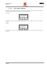
Page 130: ...n digital inputs MDI1 MDI2 MDI3 see Operation Method submenu Access page Press PROG Ent to access the first page of the Multispeed submenu Press Nxt and Prv to scroll through the submenus First page Press PROG Esc to return to the Multispeed submenu access page Press Nxt and Prv to scroll through the parameters PROG SAVE Menu Multispeed Ent Prv Nxt PROG SAVE Multispeed 1 9 Esc Prv Nxt ...

Page 131: ...m D 0 speed2 rpm F Determines the speed reference obtained when multifunction digital input 2 terminal 10 is active and set as multispeed parameter C18 OP METHOD submenu P42 Multispd 5 9 P P42 R 9000 9000 rpm D 0 speed3 rpm F Determines the speed reference obtained when multifunction digital inputs 1 and 2 terminals 9 and 10 are active and set as multispeed par C17 and C18 OP METHOD submenu P43 Mu...

Page 132: ...e active and set as multispeed par C18 and C19 OP METHOD submenu P46 Multispd 9 9 P P46 R 9000 9000 rpm D 0 speed7 F Determines the speed reference obtained when multifunction digital inputs 1 2 and 3 terminals 9 10 and 11 are active and set as multispeed par C17 C18 and C19 OP METHOD submenu NOTE The preset speed reference cannot exceed the maximum speed value set through parameter C02 Spdmax ...

Page 133: ...e is an absolute value i e is not depending on the direction of rotation Set it to 0 to disable the prohibit speed range P56 Prohib s 3 5 P P56 R 0 9000 rpm D 0 speed2 rpm F Determines the intermediate value for the second prohibit speed range The intermediate value is an absolute value i e is not depending on the direction of rotation Set it to 0 to disable the prohibit speed range P57 Prohib s 4...

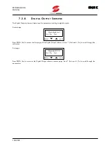
Page 134: ...puts Access page Press PROG Ent to access the first page of the Digital Output submenu Press Nxt and Prv to scroll through the submenus First page Press PROG Esc to return to the Digital Output submenu access page Press Nxt and Prv to scroll through the parameters PROG SAVE Menu digital out Ent Prv Nxt PROG SAVE Dig output 1 16 Ent Prv Nxt ...

Page 135: ...e Motor limiting active output inverter limited by the motor Generator lim active output limit during braking stage PID OK active output if the absolute value of the difference between the reference signal and PID regulator feedback has dropped below a threshold set with P69 MDO Level PID OUT MAX 0 active output if PID regulator output has reached the value set for P90 PID MAX Out see Fig 6 6 PID ...

Page 136: ...ator light or to send emergency signals to the PLC If Inv run trip is selected the digital output activates only if the inverter enters the emergency mode due to a protection trip Turn off and on the equipment in emergency mode to deactivate the digital output In this operating mode the digital output may be used to control a relay activating a contactor installed on the inverter supply line The c...

Page 137: ...ing active output inverter limited by the motor Generator lim active output limit during braking stage PID OK active output if the absolute value of the difference between the reference signal and PID regulator feedback has dropped below a threshold set with P71 RL1 Level PID OUT MAX 0 active output if PID regulator output has reached the value set for P90 PID MAX Out see Fig 6 6 PID OUT MIN activ...

Page 138: ...y be used to control an indicator light or to send emergency signals to the PLC If Inv run trip is selected the digital output activates only if the inverter enters the emergency mode due to a protection trip Turn off and on the equipment in emergency mode to deactivate the digital output In this operating mode the digital output may be used to control a relay activating a contactor installed on t...

Page 139: ... active output inverter limited by the motor Generator lim active output limit during braking stage PID OK active output if the absolute value of the difference between the reference signal and PID regulator feedback has dropped below a threshold set with P73 RL2 Level PID OUT MAX 0 active output if PID regulator output has reached the value set for P90 PID MAX Out see Fig 6 6 PID OUT MIN active o...

Page 140: ...ing mode the digital output may be used to control a relay activating a contactor installed on the inverter supply line NOTE Use parameter P74 to set a hysteresis for the commutation of a digital output P63 MDO ON 5 19 P P63 R 0 0 650 0 s D 0s delay s F Determines the activation delay of Open Collector digital output P64 MDO OFF 6 19 P P64 D 0s R 0 0 650 0 s delay s F Determines the deactivation d...

Page 141: ...s commutation occurs when the value set in P69 P70 is reached Example Set P60 Speed level P69 50 P70 10 the digital output activation occurs when 50 of the preset maximum speed is reached deactivation occurs when 40 is reached If P70 0 commutation occurs when the value set in P69 is reached Open Collector MDO digital output set as PID Max Out and PID Min Out determines the value for the digital ou...

Page 142: ... 200 D 5 level F Determines the value for the activation of relay digital output RL2 for the following settings Rmpout level Reference Level Speed level Forward Running Reverse Running Tq out level Current Level FB Max FB Min Speedout O K e PID O K P74 RL2 16 19 P P74 R 0 200 D 2 hyst F When relay digital output RL2 is set as Rmpout Level Reference Level Speed level Forward Running Reverse Running...

Page 143: ...Torque 19 19 P P77 R 0 400 Important the maximum programmable value is equal to Imax Imot 100 see Table 7 4 D 100 lift F Torque value for the output activation in mode Lift 7 2 9 PID REGULATOR SUBMENU The PID Regulator submenu includes PID regulator adjusting parameters Access page Press PROG Ent to access the first page of the PID Regulator submenu Press Nxt and Prv to scroll through the submenus...

Page 144: ...Integr Time NONE value following 1024 to override integral action P88Deriv 5 13 P P88 R 0 4 Tc D 0 Tc Time Tc F Constant multiplying PID regulator derivative term It is expressed as a multiple value of the sampling time Set Deriv Time 0 to override derivative action P89 PID min 6 13 P P89 R 100 100 D 0 Out F Minimum value of PID regulator output P90 PID max 7 13 P P90 R 100 100 D 100 Out F Maximum...

Page 145: ...ximum value of PID regulator derivative term P96 PID dis 13 13 P P96 R 0 60000 Tc D 0 Tc time s F The inverter stops if the output value of PID regulator remains equal to the minimum value parameter P89 for the time set in P96 Set P96 to 0 Tc to disable this function NOTE For further details on how to use functionality of the PID REGULATOR menu see section 3 12 VTC ...

Page 146: ...nd Prv to scroll through the parameters PARAMETERS OF THE SPEED LOOP SUBMENU P100 Spd Prop2 4 P P100 R 0 32 D 5 0 gain F Defines the value of speed regulator proportional term P101 Spd lnt 3 4 P P101 R 0 10 s NONE D 0 5 s time s F Defines the value of speed regulator integral time Set NONE to disable integral term 102 ZeroSpd 4 4 P P102 R 0 500 D 100 const F Multiplicative constant of the proporti...

Page 147: ...rv to scroll through the submenus First page Press PROG Esc to return to the Torque Ramp submenu access page Press Nxt and Prv to scroll through the parameters PARAMETERS OF THE TORQUE RAMPS SUBMENU P105 Ramp Up 2 3 P P105 R 0 6500s D 0s Time s F Determines the rise ramp time of the torque reference P106 Ramp Dn 3 3 P P106 R 0 6500s D 0 s Time s F Determines the fall ramp time of the torque refere...

Page 148: ...age of the VTC Pattern submenu Press Nxt and Prv to scroll through the submenus First page Press PROG Esc to return to the VTC Pattern submenu access page Press Nxt and Prv to scroll through the parameters PARAMETERS OF THE VTC PATTERN SUBMENU C01 VTC Patt 2 13 P C01 R 5 150 Hz D 50 Hz fmot Hz F Motor rated frequency Determines the speed for the commutation to flux weakening operating mode C02 VTC...

Page 149: ...ist ohm F Rotor winding resistance With a star connection C08 corresponds to the resistance value of one phase half the resistance measured between two terminals with a delta connection C08 corresponds to 1 3 of the phase resistance half the value measured between two terminals C09 Leakage 10 13 P C09 R 0 100 mH D Column C09 default Table 7 4 Induct mH F Value of the motor full leakage inductance ...

Page 150: ...ypad see COMMANDS menu terminal 7 is inactive all other digital inputs are active Rem the START command and the commands relating to multifunction digital inputs are sent via serial link NOTE The inverter runs only if terminal 6 is active Therefore terminal 6 must ALWAYS be closed independently of par C14 programming C15 Op Meth 3 16 P C15 R Speed Torque D Speed Command F Determines main reference...

Page 151: ... setting in KeyPad position C19 Op Meth 7 16 P C19 R Mlts3 CW CCW DCB REV A M Lock Slave Loc Rem D Mlts3 Determines functionality of multifunction input 3 terminal 11 Mlts3 multispeed input 3 CW CCW reversal of the direction of rotation DCB direct current braking command REV reverse rotation command A M PID regulator deactivation command Lock keypad lock command MDI3 F Loc Rem setting in KeyPad po...

Page 152: ...Kpd Vref Iref Inaux Rem D Kpd Determines the source of PID regulator reference Kpd keypad Vref voltage terminals terminals 2 and 3 Iref current terminals terminal 21 Inaux voltage terminals through auxiliary input terminal 19 Ref F Rem serial link NOTE Setting C23 Vref deletes the speed reference from Term C24 PID 12 16 P C24 R Inaux Vref Iref Iout D Inaux Determines the source of PID regulator fe...

Page 153: ...d after a stop command until the deceleration ramp is over time set in C51 is over and the inverter is disabled Set C27 0 to disable this function If C51 is set to 0 the run command is locked because the sequence cannot be terminated Always set C51 other than 0 when using this function C28 PIDinv 16 16 P C28 R NO YES D NO NO YES F If C28 YES is programmed it adds a unit negative gain to the PID lo...

Page 154: ...S YES V D NO Enables motor power down in case of mains failure NO function disabled YES motor power down in case of mains failure once the time set in C36 is over F YES V like YES with an automatic deceleration ramp to keep DC voltage constant at the value set in C33 with C34 proportional and C35 integral C33 Voltage 3 9 P C33 R 200 800 V D 368 V class 2T D 640 V class 4T level V F DC voltage valu...

Page 155: ...tion in case of mains failure C37 PD Dec 7 9 P C37 R 0 1 6500 s D 10 s time F Deceleration ramp during power down C38 PD Extra 8 9 P C38 R 0 500 D 200 dec F Speeding of deceleration ramp during the first stage of power down condition C39 PD Link 9 9 P C39 R 0 300 D 0 der F Speeds up mains failure detection to enable motor power down VTC ...

Page 156: ...page Press Nxt and Prv to scroll through the parameters PARAMETERS OF THE LIMITS SUBMENU C42 Torque 2 3 P C42 R 50 400 Important the maximum programmable value is equal to Imax Imot 100 see Table 7 4 D See Table 7 4 HEAVY overload run F Torque limit expressed as a percentage of the motor rated torque calculated based on VTC pattern menu parameters C43 Trq Var 3 3 P C43 R NO YES D NO NO YES F Enabl...

Page 157: ... PARAMETERS OF THE AUTORESET SUBMENU C46 Attempts 2 4 P C46 R 0 10 D 0 Number F Determines the number of automatic reset operations performed before locking the function Autoreset count starts from 0 after a time period longer than the one set in C52 is over NOTE If C46 0 is set the autoreset function is locked C47 Clear fail 3 4 P C47 R 1 999s D 300s count time s F Determines the time interval cl...

Page 158: ...d Prv to scroll through the submenus First page Press PROG Esc to return to the Special Function submenu access page Press Nxt and Prv to scroll through the parameters PARAMETERS OF THE SPECIAL FUNCTION SUBMENU C49 MainsNom 2 17 P C49 R 200 240V cannot be altered class 2T 380 480V 481 500V class 4T D 200 240V class 2T 380 480V class 4T Sets the range for the rated mains voltage This parameters aff...

Page 159: ...y alarm relating to mains failure A30 and A31 causing the equipment power off When power supply is restored send a RESET command to reset the alarms tripped C53 ENABLE 6 17 P C53 NO YES R NO YES D YES F Operating conditions of ENABLE command terminal 6 at power on or when a RESET command is sent NO ENABLE command deactivated at power on or after RESET if terminals 6 and 7 are active and a speed re...

Page 160: ... M13 Time period of RUN mode after startup Hist 1 M14 Last alarm tripped Hist 2 M15 Last but one alarm tripped Hist 3 M16 Last but two alarm tripped Hist 4 M17 Last but three alarm tripped Hist 5 M18 Last but four alarm tripped Aux I M19 Auxiliary input value Pid Rf M20 PID regulator reference value Pid FB M21 PID regulator feedback value Pid Er M22 Difference between reference and feedback of PID...

Page 161: ...ld trip depends on formula C02 C02 C61 100 If set to 0 this function is disabled C62 DCB ramp 15 17 P C62 R 2 255 ms D 100 ms time ms F Flux decreasing ramp before DCB C63 Flux 16 17 P C63 R 30 4000 ms D 300 ms for S05 S30 D 450 ms for S40 S70 ramp ms F Motor flux ramp C64 Flux 17 17 P C63 R 0 4000 ms D 0 ms delay ms F Delay time after motor flux ramp before enabling motor startup This parameter m...

Page 162: ...ECTION SUBMENU C65 Thermal p 2 6 P C65 R NO YES YES A YES B D NO Activates the motor thermal protection NO Motor thermal protection disabled YES Motor thermal protection enabled with pick up current independent of motor frequency YES A Motor thermal protection enabled with pick up current depending on motor speed with forced air cooling system prot F YES B Motor thermal protection enabled with pic...

Page 163: ...aking submenu includes the parameters relating to direct current braking For more details see section 3 9 DIRECT CURRENT BRAKING Access page Press PROG Ent to access the first page of the D C Braking submenu Press Nxt and Prv to scroll through the submenus First page Press PROG Esc to return to the D C Braking submenu access page Press Nxt and Prv to scroll through the parameters PARAMETERS OF THE...

Page 164: ... VIA TERMINAL BOARD C73 DCB Time 5 7 P C73 R 0 1 50s D 0 5s at Start s F Determines DC braking time period before the acceleration ramp C74 DCB Spd 6 7 P C74 R 0 300 rpm D 50 rpm at Stop rpm F Determines the motor speed for DC braking at stop and affects the formula expressing DC braking time period with a command sent via terminal board see section 3 9 3 DC BRAKING COMMAND SENT VIA TERMINAL BOARD...

Page 165: ...ink Access page Press PROG Ent to access the first page of the Serial Network submenu Press Nxt and Prv to scroll through the submenus First page Press PROG Esc to return to the Serial Network submenu access page Press Nxt and Prv to scroll through the parameters PROG SAVE Menu Serial net Ent Prv Nxt PROG SAVE Serial netw 1 7 Ent Prv Nxt VTC ...

Page 166: ...d message is received within 5s Alarm A40 Serial communication error is displayed C83 RTU Time 5 7 P C83 R 0 2000 ms D 0 ms out ms F When the inverter is ready to receive the message sent from the master is considered as complete and processed if no character is received within the time set through C83 C84 Baud 6 7 P C84 R 1200 2400 4800 9600 baud D 9600 baud rate baud F Sets the baud rate as bits...

Page 167: ... 40 1 41 72 0 25 0 19 2 150 S15 0038 26 45 6 65 75 0 2 0 15 2 150 S15 0040 26 45 6 72 75 0 2 0 15 2 150 S20 0049 30 56 1 80 96 0 15 0 115 2 150 S20 0060 37 67 7 88 112 0 12 0 09 2 150 S20 0067 45 78 7 103 118 0 1 0 075 1 2 149 S20 0072 48 83 9 120 144 0 08 0 06 1 2 150 S20 0086 55 96 3 135 155 0 06 0 045 1 150 S30 0113 75 134 8 180 200 0 04 0 03 1 148 S30 0129 80 143 8 195 215 0 04 0 03 1 149 S30 ...

Page 168: ...terisk appears if at least one condition requiring the activation of a protection feature occurs when the inverter is running in Fire Mode 2 If the equipment is enabled when the ENABLE input is closed and parameter C61 IFD SW or C53 VTC SW is set to NO the following message is displayed 3 If the output frequency is constant other than zero and equal to the reference IFD SW or the inverter is in RU...

Page 169: ... decelerating 8 If the output frequency IFD SW or the motor speed VTC SW is under the reference value for current limit activation IFD SW or torque limit activation VTC SW at constant frequency 9 When the operation of built in braking module exceeds the time periods set through parameters C67 C68 IFD SW or C59 C60 VTC SW 10 With POWER DOWN see section 3 8 NOTE NOTE Steps 3 4 5 6 7 8 9 10 VTC SW di...

Page 170: ...C SW only 15 When the inverter is running in Fire Mode once the output frequency set with parameter P38 IFD SW only is attained If faults occur the display shows The display LEDs start flashing alarm messages detailed in section 8 2 may be displayed PROG SAVE BRAKING A M P Cfg Cm Srv PROG SAVE TUNING A M P Cfg Cm Srv PROG SAVE SEARCH Hz M P Cfg Cm Srv PROG SAVE FLUXING A M P Cfg Cm Srv PROG SAVE I...

Page 171: ...ared as it is stored to EEPROM The alarm tripped is displayed at next power on and the inverter is still locked Close reset contact or press the RESET button Alarm reset is also possible by turning off and on the inverter and by setting parameter C53 to YES SW IFD or parameter C48 VTC SW to YES PWR Reset ...

Page 172: ...roller failure SOLUTION Reset the alarm If the alarm condition persists please contact ELETTRONICA SANTERNO s AFTER SALES SERVICE A11 Bypass circ failure Faulty relay or contactor for the short circuit of precharge resistors for DC link capacitors SOLUTION Reset the alarm If the alarm condition persists please contact ELETTRONICA SANTERNO s AFTER SALES SERVICE A15 ENCODER Alarm VTC SW only Alarm A...

Page 173: ... over A24 Motor not connected VTC SW only Alarm A24 trips during autotuning or DCB stage if the motor is not connected or does not match with the inverter size rated power lower than minimum programmable value for C04 A25 Mains loss IFD SW only Mains failure Alarm A25 is active only if parameter C34 is set to YES factory setting is NO This alarm may be delayed through parameter C36 Power delay tim...

Page 174: ...lerating SOLUTION This alarm trips if a too short deceleration ramp is programmed If so set longer deceleration time periods P06 P08 P10 P12 RAMPS submenu and decrease BOOST and PREBOOST V F PATTERN submenu parameters C10 and C11 or parameters C16 and C17 if the second V F pattern is used for IFD SW Decrease torque limit value C42 for VTC SW A27 SW Searching overcurrent IFD SW only A35 Searching o...

Page 175: ...oard or no communication link between inverter and keypad Blinking Off Communication failure between microcontroller and DSP in the control board Off Blinking Errors occurred in the RAM U47 in the control board Blinking Blinking User interface FLASH see jumper J15 is set up with a different SW type than the motor control DSP see jumper J19 IFD SW for FLASH and VTC SW for DSP or viceversa Do the fo...

Page 176: ...r will consider this time interval as the end of the message Similarly a message starting with a shorter silence time is considered as a part of the previous message Message beginning Address Function Data Error control End of message T1 T2 T3 T4 8 bits 8 bits n x 8 bits 16 bits T1 T2 T3 T4 Use parameter C93 TimeOut IFD SW or parameter C83 VTC SW to increase the silence time interval up to max 200...

Page 177: ...byte Supported Functions 03h Read Holding Register Allows to read the register state of the slave device This function does not allow the broadcast mode address 0 Additional parameters are the address of the basic digital register to be read and the output number to be read QUERY RESPONSE Slave address Slave address Function 03h Function 03h Register address high Byte number Register address low D...

Page 178: ...n Max columns 06h SLAVE DEVICE BUSY The slave cannot accept writing 1 you attempted to write a Cxx parameter when the inverter was in RUN mode 2 a long lasting operation is occurring e g Restore Default 9 3 GENERAL FEATURES and EXAMPLES Parameters are queried along with the reading performed through the inverter keypad and display Parameter alteration is also managed along with the inverter keypad...

Page 179: ... or class voltage are grouped as follows Table T000 index SW3 at address 477 1DDh I full scale A Max freq out Hz Def carrier Max carrier Def preboost T000 0 T000 1 T000 2 T000 3 T000 4 0 25 800 7 12 1 1 50 800 7 12 1 2 65 800 5 12 1 Table reading Name Description Addr dec READ Addr hex READ Min Max K Unit of measure M03 IOUT Output current 1026 402 50 65536 T000 0 1307 A Because K 50 65536 T000 0 ...

Page 180: ...5 MSB To set P39 write 1 to address 512 dec write 0 to the same address to reset P39 For peculiar reading writing refer to Notes in the following tables 9 3 3 SUPPORT VARIABLES For very long formulas you can use support variables to split them into two or multiple simpler forms The example below relates to parameter SP03 for VTC SW SP03 Serial Ref 770 302 0 IF_C15 0_ C02_ ELSE_ C42 IF_C15 0_ C02_ ...

Page 181: ...C58 120 C59 rpm M11 OP T Operation time 1032 1033 408 409 5 Note 03 s M12 1st alarm Fault list 1 1034 1035 40A 40B 5 Note 04 s M13 2nd alarm Fault list 2 10361037 40C 40D 5 Note 04 s M14 3rd alarm Fault list 3 10381039 40E 40F 5 Note 04 s M15 4th alarm Fault list 4 10401041 410 411 5 Note 04 s M16 5th alarm Fault list 5 10421043 412 413 5 Note 04 s M17 AUX I Auxiliary analog input 1044 414 4096 10...

Page 182: ...he word to the lower address The higher byte of the word to the higher address includes the alarm number coded as in Note 12 inverter state see Note 12 The last alarm displayed in parameter M12 is the alarm with the longest time period The other alarms are displayed up to M16 with the shortest time period 10 2 PROGRAMMING PARAMETERS Pxx Read Write 10 2 1 RAMPS MENU P0X P1X Name Description Addr de...

Page 183: ...5120 500 P21 AUX B Reference with auxiliary input at 0 14 E 0 400 400 16384 400 P22 AUX G Factor between auxiliary input and reference 15 F 200 400 400 16384 400 P26 DIS TIME Ref disabling time at minimum 16 10 0 0 120 1 s Note 05 Range 0 to T000 1 Hz Value 0 1 corresponds to value on the display Reference Menu P1x P2x Bit Parameters Name Description Addr dec R W Addr hex R W Def Min Max K Unit of...

Page 184: ...Hz V P33 KOI Constant for analog output current 20 14 25 T000 0 500 6 T000 0 500 100 T000 0 500 500 T000 0 A V P34 KOV Constant for analog output voltage 21 15 100 20 100 1 V V P35 KOP Constant for analog output power 22 16 25 T000 0 500 6 T000 0 500 40 T000 0 500 500 T000 0 kW V P36 KON Constant for analog output speed 23 17 200 90 C59 10000 C59 1 C59 rpm V P37 KOR Constant for analog output PID ...

Page 185: ...9 MLTF 33 21 0 T000 1 T000 1 10 Hz P49 FREQ10 Output frequency 10 MLTF 34 22 0 T000 1 T000 1 10 Hz P50 FREQ11 Output frequency 11 MLTF 35 23 0 T000 1 T000 1 10 Hz P51 FREQ12 Output frequency 12 MLTF 36 24 0 T000 1 T000 1 10 Hz P52 FREQ13 Output frequency 13 MLTF 37 25 0 T000 1 T000 1 10 Hz P53 FREQ14 Output frequency 14 MLTF 38 26 0 T000 1 T000 1 10 Hz P54 FREQ15 Output frequency 15 MLTF 39 27 0 T...

Page 186: ...enabling delay 51 33 0 0 650 10 s P68 RL2 OFF DELAY Relay output RL2 disabling delay 52 34 0 0 650 10 s P69 MDO LEVEL O C output enabling level 53 35 0 0 200 10 P70 MDO HYS O C output disabling hysteresis 54 36 0 0 200 10 P71 RL1 LEVEL Relay output RL1 enabling level 55 37 0 0 200 10 P72 RL1 HYS Relay output RL1 disabling hysteresis 56 38 0 0 200 10 P73 RL2 LEVEL Relay output RL2 enabling level 57...

Page 187: ...2 0 002 4 500 s P86 KP Proportional gain 67 43 1 0 31 999 1024 P87 TI Integral time 68 44 512 3 1025 Note 06 1 Tc P88 TD Derivative time 69 45 0 0 4 256 Tc P89 PID MIN PID output min value 70 46 0 100 100 20 P90 PID MAX PID output max value 71 47 100 100 100 20 P91 PID R A Increasing time over the PID reference 72 48 0 0 6500 10 s P92 PID R D Decreasing time over the PID reference 73 49 0 0 6500 1...

Page 188: ...X Max carrier frequency 1281 501 T000 2 C01 T000 3 List C03PULSE N Pulse number 1282 502 1 0 5 List List for parameters C01 and C02 0 0 8 kHz 1 1 0 kHz 2 1 2 kHz 3 1 8 kHz 4 2 0 kHz 5 3 0 kHz 6 4 0 kHz 7 5 0 kHz 8 6 0 kHz 9 8 0 kHz 10 10 0 kHz 11 12 8 kHz 12 16 0 kHz List for parameter C03 0 12 1 24 2 48 3 96 4 192 5 384 Carrier Frequency Menu C0x Bit Parameters Name Description Addr dec WRITE Add...

Page 189: ...T 6T 1 V C16 BOOST2 Torque compensation 2 1293 50D 0 100 100 1 C17 PREBST2 Torque compensation at 0Hz 2 1294 50E T000 4 0 5 10 C18 AUTOBST Automatic torque compensation 1336 530 1 0 10 10 C19 B MF Compensazione di coppia intermedia 1 1341 53D 0 100 400 1 C20 FBOOST MF Freq attuazione compensazione di coppia intermedia 1 1340 53C 50 6 99 1 10 3 3 OPERATION METHOD MENU C1X C2X Name Description Addr ...

Page 190: ... A M 6 Lock 7 Loc Rem List for parameter C26 0 Mltf4 1 Mltr1 2 DCB 3 CWCCW 4 REV 5 A M 6 Lock 7 Loc Rem List for parameter C27 0 DCB 1 Mltr2 2 CWCCW 3 Vf2 4 Ext A 5 REV 6 Lock 7 Fire Mode List for parameter C28 0 Ext 1 Ref F 2 Add F 3 Add V List for parameter C29 0 Kpd 1 Vref 2 Inaux 3 Iref 4 Rem ...

Page 191: ...de the inverter acknowledges the inputs simulated by the master device SP00 via serial link instead of the terminal board inputs Note 08 In Rem mode the inverter acknowledges the reference sent by the master device SP02 via serial link instead of the reference sent from the terminal board C21 bit 773 11 bit 772 4 Kpd 0 0 Term 0 1 Rem 1 1 C22 bit 773 12 bit 772 5 Kpd 0 0 Term 0 1 Rem 1 1 10 3 4 POW...

Page 192: ...50 50 MIN T002 2 100 C05 400 1 C45DEC CURR Lim current while deceleration 1309 51D IF_T000 10_ MIN T002 2 100 C05 150 _ ELSE_ MIN T002 2 100 C05 120 50 IF_T000 10_ MIN T002 2 100 C05 400 _ ELSE_ MIN T002 2 100 C05 120 1 Limits Menu C4x Bit Parameters Name Description Addr dec WRITE Addr hex WRITE Addr dec READ Addr hex READ Def Min Max C40ACC LIM Acceleration limit enabling bit 772 8 520 208 772 8...

Page 193: ...OLES Poles 1313 521 4 2 16 0 5 C59RED R Reduction ratio 1314 522 1 0 001 50 1000 C63FIRST PARAM First parameter at power on 1315 523 1 0 21 List C64FB R Feedback ratio 1316 524 1 0 001 50 1000 C65SEARCH R Searching rate 1317 525 100 10 999 1 C66SEARCH C Searching current 1318 526 75 40 MIN T002 2 100 C05 400 1 C67Brk Disable Brake disabling time 1319 527 18000 0 65400 1 ms C68Brk enable Brake enab...

Page 194: ...e at power on 514 202 772 2 304 2 0 0 1 C69BRK BOOST Extrafluxing for deceleration ramp 542 21E 773 14 305 14 1 0 1 C55 bit 773 2 bit 772 12 NO 0 0 Yes 0 1 Yes A 1 1 10 3 8 MOTOR THERMAL PROTECTION MENU C6X Name Description Addr dec R W Addr hex R W Def Min Max K Unit of meas C65THR PRO Thermal protection enabling 1321 529 0 0 3 List C66MOT CUR Thermal protection pick up current 1322 52A 105 1 120...

Page 195: ...81DCB AT START DCB at START enabling 526 20E 772 14 304 14 0 0 1 C86DCB HOLD DCB holding enabling 519 207 772 7 304 7 0 0 1 10 3 11 SERIAL LINK MENU C9X Name Description Addr dec R W Addr hex R W Def Min Max K Unit of meas C90ADDRESS Inverter address 1332 52C 1 1 247 1 C91S DELAY Response delay 1333 52D 0 0 500 20 ms C93RTU Timeout MODBUS RTU serial time out 1334 52E 0 0 2000 1 ms C94BaudRate Seri...

Page 196: ...abled 1 Enabled C31 PID INVERSION 10 0 Disabled 1 Enabled C50 AUTORESET 10 0 Disabled 1 Enabled C60 MAINS LOSS MEM 11 0 Not stored 1 Stored C55 SPEED SEARCHING 12 Along with bit 773 2 C80 DCB AT STOP 13 0 Disabled 1 Enabled C81 DCB AT START 14 0 Disabled 1 Enabled C61 ENABLE OPERATION 15 0 Activated after opening 1 Immediately activated Note 11 SP05 Configuration bit address 773 305 hex Bit P24 UP...

Page 197: ...ass circ failure 12 A01 Wrong software 13 A26 Running overcurrent SW 14 TO START OPEN AND CLOSE TERM6 15 A27 Searching overcurrent SW 16 A21 Heatsink overheated 17 A06 Microcontroller Failure 18 A32 Running overcurrent 19 A33 Accelerating overcurrent 20 A34 Decelerating overcurrent 21 A35 Searching overcurrent 22 A40 Serial comm error 23 A28 Accelerating overcurrent SW 24 A29 Decelerating overcurr...

Page 198: ...s simulated via serial link 768 300 Note 15 SP02 Serial reference 770 302 0 Note 16 Note 16 10 Hz SP03 Serial PID reference 771 303 0 100 100 20 SP10 Parameter saving 778 30A Note 17 SP11 Default restoration 779 30B Note 18 Note 15 Terminals are simulated by sending a byte to the inverter the byte bits simulate the active state of an input Structure is the same as the one stated in Note 01 see Not...

Page 199: ...25 800 7 12 1 1 50 800 7 12 1 2 65 800 7 12 1 3 100 800 5 12 1 4 125 800 5 12 1 5 130 800 7 12 1 6 210 800 7 11 1 7 280 800 7 11 1 8 390 800 5 10 0 5 9 480 800 5 7 0 5 10 650 120 4 6 0 5 11 865 120 4 6 0 5 12 1300 120 4 6 0 5 13 1750 120 4 6 0 5 14 1875 120 4 6 0 5 15 2640 120 4 6 0 5 Table T001 index SW5 at address 479 1DFh Class V T001 0 0 230 2T or 575 5T 1 400 4T or 690 6T IFD ...

Page 200: ...0 086 14 SINUS K 0060 67 7 88 112 37 0 21 3 0 120 0 069 15 SINUS K 0067 78 7 103 118 45 0 25 9 0 100 0 057 16 SINUS K 0074 83 9 120 144 48 0 27 7 0 080 0 046 17 SINUS K 0086 96 3 135 155 55 0 31 7 0 060 0 034 18 SINUS K 0113 134 8 180 200 75 0 43 3 0 040 0 023 19 SINUS K 0129 143 8 195 215 80 0 46 1 0 040 0 023 20 SINUS K 0150 162 8 215 270 90 0 51 9 0 030 0 017 21 SINUS K 0162 194 2 240 290 110 0...

Page 201: ... 13 SINUS K 0049 0 0 0 0 0 0 0 0 14 SINUS K 0060 0 0 0 0 0 0 0 0 15 SINUS K 0067 0 0 0 0 0 0 0 0 16 SINUS K 0074 0 0 0 0 0 0 0 0 17 SINUS K 0086 0 0 0 0 0 0 0 0 18 SINUS K 0113 0 0 0 0 0 0 0 0 19 SINUS K 0129 0 0 0 0 0 0 0 0 20 SINUS K 0150 0 0 0 0 0 0 0 0 21 SINUS K 0162 0 0 0 0 0 0 0 0 22 SINUS K 0179 0 0 0 0 0 0 0 0 23 SINUS K 0200 0 0 0 0 0 0 0 0 24 SINUS K 0216 0 0 0 0 0 0 0 0 25 SINUS K 0250...

Page 202: ...tage 1032 408 1024 1000 V M10 POUT Output power 1033 409 655 100 T000 0 kW M11 Term B Digital inputs 768 300 Note 01 M12 TB Out Digital outputs 778 30A Note 02 M13 OP T Operation time 1034 1035 40A 40B 5 Note 03 s M14 1st alarm Fault list 1 1036 1037 40C 40D 5 Note 04 s M15 2nd alarm Fault list 2 1038 1039 40E 40F 5 Note 04 s M16 3rd alarm Fault list 3 1040 1041 410 411 5 Note 04 s M17 4th alarm F...

Page 203: ...ord to the lower address The higher byte of the word to the higher address includes the alarm number coded as in Note 14 inverter state see Note 12 The last alarm displayed in parameter M14 is the alarm with the longest time period The other alarms are displayed up to M18 with the shorter time period 11 2 PROGRAMMING PARAMETERS Pxx Read Write 11 2 1 RAMPS MENU P0X P1X Name Description Addr dec R W...

Page 204: ...eference with auxiliary input at 0 15 F 0 400 400 16384 400 P22 AUX G Factor between auxiliary input and reference 16 10 200 400 400 16384 400 P26 DIS TIME Disabling time 17 11 0 0 120 1 s Note 05 Range 0 to 9000 rpm Value 1 corresponds to value on the display Reference Menu P1x P2x Bit Parameters Name Description Addr dec WRITE Addr hex WRITE Addr dec READ Addr hex READ Def Min Max P18 VREF J14 P...

Page 205: ...16 25 T000 0 500 6 T000 0 500 100 T000 0 500 500 T000 0 A V P33 KOV Analog output constant voltage 23 17 100 20 100 1 V V P34 KOP Analog output constant power 24 18 25 T000 0 600 6 T000 0 600 40 T000 0 600 600 T000 0 kW V P35 KON Analog output constant speed 25 19 200 50 5000 1 rpm V P36 KOT Analog output constant torque 26 1A 10 5 100 1 V P37 KOR Analog output constant PID output 27 1B 10 2 5 50 ...

Page 206: ...P45 MLTS 6 Speed reference 6 MLTS 33 21 0 9000 9000 1024 1194 rpm P46 MLTS 7 Speed reference 7 MLTS 34 22 0 9000 9000 1024 1194 rpm Multispeed Menu P3x P4x Bit Parameters Name Description Addr dec WRITE Addr hex WRITE Addr dec READ Addr hex READ Def Min Max P39 MS FUNCTION Use of parameters P40 P46 512 200 772 0 304 0 0 0 1 11 2 5 PROHIBIT SPEED MENU P5X Name Description Addr dec R W Addr hex R W ...

Page 207: ...P69 MDO LEVEL O C output enabling level 48 30 0 0 200 10 P70 MDO HYS O C output disabling hysteresis 49 31 0 0 200 10 P71 RL1 LEVEL Relay output RL1 enabling level 50 32 0 0 200 10 P72 RL1 HYS Relay output RL1 disabling hysteresis 51 33 0 0 200 10 P73 RL2 LEVEL Relay output RL2 enabling level 52 34 5 0 200 10 P74 RL2 HYS Relay output RL2 disabling hysteresis 53 35 2 0 200 10 P75 LIFT LEVEL Lift le...

Page 208: ...ue 66 42 100 0 100 20 P95 MAX D Derivative term max absolute value 67 43 10 0 10 20 P96 PID DIS TIME PID reset counting at min value 68 44 0 0 60000 1 Tc Note 06 Integral time is expressed as a multiple value of sampling time P85 Real integral time is P85 P87 upper value is 1024 1025 disables integral adjustment 11 2 8 SPEED LOOP MENU P10X Name Description Addr dec R W Addr hex R W Def Min Max K U...

Page 209: ..._ ELSE_T002 3 4 IF_ SW5 0_ T002 7 2_ ELSE_T002 3 2 10 kW C05IMOT Motor rated current 1284 504 T002 0 T002 1 4 T002 1 10 A C06SPDNOM Motor rated speed 1285 505 1420 0 9000 1 rpm C07STATOR Stator resistance 1286 506 IF_SW5 0_ T002 8 _ ELSE_T002 4 0 30 1000 ohm C08ROTOR Rotor resistance 1287 507 IF_SW5 0_ T002 9 ELSE_ T002 5 0 30 1000 ohm C09LEAKAGE Leakage inductance 1288 508 IF_SW5 0_ T002 10 ELSE_...

Page 210: ...1294 50E 0 0 6 List C22PID ACT PID operating mode 1295 50F 0 0 2 List C23PID REF PID reference selection 1296 510 0 0 4 List C24PID FB PID feedback selection 1297 511 1 0 3 List C26ENC STEP Encoder pulse number 1298 512 1024 100 10000 1 C27Delay Spd Run delay threshold 1329 531 0 0 1500 1 rpm List for parameter C17 0 Mlts1 1 UP 2 Stop 3 Slave List for parameter C18 0 Mlts2 1 DOWN 2 Slave 3 Loc Rem...

Page 211: ... 5 304 5 1 0 1 C14REM ENABLE START command function Note 08 535 217 773 7 305 7 0 0 1 C16REF ENABLE REF enable from serial Note 09 536 218 773 8 305 8 0 0 1 C15SPD TRQ SPD TRQ control mode 544 220 774 7 306 7 0 0 1 C25ENC Encoder feedback bit 774 1 538 21A 774 1 306 2 0 0 1 C25ENC Encoder feedback bit 774 9 546 222 774 9 306 9 0 0 1 C28 PID INV PID error inversion 522 20A 772 10 304 10 0 0 1 Note ...

Page 212: ...R DOWN loop Kp constant 1300 514 512 0 32000 1 C35V Ki POWER DOWN loop Ki constant 1301 515 512 0 32000 1 C36PD Delay Power down delay 1302 516 10 5 255 1 ms C37PD DEC T Deceleration time during power down 1303 517 10 0 1 6500 10 s C38PDEXTRA Extra deceleration during power down 1304 518 200 0 500 32 100 C39DC LINK D Power failure detection speed increase 1305 519 0 0 300 256 100 Power Down Menu C...

Page 213: ...c WRITE Addr hex WRITE Addr dec READ Addr hex READ Def Min Max C43TRQ VAR Torque limit with IN AUX 537 219 774 0 306 0 0 0 1 11 3 5 AUTORESET MENU C4X Name Description Addr dec R W Addr hex R W Def Min Max K Unit of meas C46ATT N Autoreset attempts 1307 51B 4 1 10 1 C47CL FAIL T Autoreset attempt reset 1308 51C 300 1 999 50 s Autoreset Menu C4x Bit Parameters Name Description Addr dec WRITE Addr h...

Page 214: ...or parameter C55 0 M01 Spd ref Tq ref 1 M02 Rmp out 2 M03 Spd out 3 M04 demand 4 M05 Tq out 5 M06 Iout 6 M07 Vout 7 M08 Vmn 8 M09 Vdc 9 M10 Pout 10 M11 Tr Bd 11 M12 TB Out 12 M13 O Time 13 M14 Hist 1 14 M15 Hist 2 15 M16 Hist 3 16 M17 Hist 4 17 M18 Hist 5 18 M19 Aux I 19 M20 Pid Rf 20 M21 Pid FB 21 M22 Pid Er 22 M23 Pid O 23 M24 Feed B Special Functions Menu C5x C6x Bit Parameters Name Description...

Page 215: ...Def Min Max K Unit of meas C72DCB T SP DCB at STOP time 1320 528 0 5 0 1 50 10 s C73DCB T ST DCB at START time 1321 529 0 5 0 1 50 10 s C74DCB SP DCB at STOP starting speed 1322 52A 50 1 250 1024 1194 rpm C75DCB CUR DCB current 1323 52B 100 1 T002 2 100 C05 1 D C Braking Menu C7x Bit Parameters Name Description Addr dec WRITE Addr hex WRITE Addr dec READ Addr hex READ Def Min Max C70DCB STP DCB at...

Page 216: ...bit 1 Even 1 stop bit 2 None 1 stop bit Serial Link Menu C8x Bit Parameters Name Description Addr dec WRITE Addr hex WRITE Addr dec READ Addr hex READ Def Min Max C82WD Communication watchdog enabling 520 208 772 8 304 8 0 0 1 11 4 SPECIAL PARAMETERS SPxx Read Only Name Description Addr dec R W Addr hex R W Def Min Max K SP02 Analog reference from terminal board 769 301 0 0 2030 1 Note 10 SP05 Con...

Page 217: ... 10 0 Disabled 1 Enabled C71 DCB AT START 14 0 Disabled 1 Enabled C53 ENABLE OPERATION 15 0 Enabled after opening 1 Immediately enabled Note 12 SP06 Configuration bit address 773 305 hex Bit P24 UP DOWN MEM 0 0 Not stored 1 Stored C70 DCB AT STOP 1 Along with bit 772 9 and 772 13 not used 2 C48 PWR RESET 3 0 Disabled 1 Enabled P25 UP DOWN RESET 4 0 Disabled 1 Enabled C32 POWER DOWN 5 Along with bi...

Page 218: ...ed 17 A06 UC Failure 18 A32 Running overcurrent 19 A33 Accelerating overcurrent 20 A34 Decelerating overcurrent 21 A02 Wrong size 22 A40 Serial comm error 23 A18 Fan fault overtemperature 24 A19 2nd sensor overtemperature 11 5 SPECIAL PARAMETERS SWxx Read Only Description Addr dec Addr hex Min Max K SW1 Software version 475 1DB Note 15 SW2 Product ID 476 1DC Note 16 SW3 AT full scale value 477 1DD...

Page 219: ...Terminals are simulated by sending a byte to the inverter the byte bits simulate the active state of an input Structure is the same as the one stated in Note 01 see Note 01 Bit 5 ENABLE is set to AND with the similar bit read from the terminal board Note 18 Any writing with any data item forces the inverter to store to EEPROM all new parameter values Note 19 Any writing with any data forces the in...

Page 220: ... 0 25 0 19 2 11 SINUS K 0038 45 6 65 75 26 0 2 0 15 2 12 SINUS K 0040 45 6 72 75 26 0 2 0 15 2 13 SINUS K 0049 56 1 80 96 30 0 15 0 115 2 14 SINUS K 0060 67 7 88 112 37 0 12 0 09 2 15 SINUS K 0067 78 7 103 118 45 0 1 0 075 1 2 16 SINUS K 0074 83 9 120 144 48 0 08 0 06 1 2 17 SINUS K 0086 96 3 135 155 55 0 06 0 045 1 18 SINUS K 0113 134 8 180 200 75 0 04 0 03 1 19 SINUS K 0129 143 8 195 215 80 0 04...

Page 221: ...2 7 0 144 0 109 1 15 11 SINUS K 0038 15 0 0 115 0 086 1 15 12 SINUS K 0040 15 0 0 115 0 086 1 15 13 SINUS K 0049 17 3 0 086 0 066 1 15 14 SINUS K 0060 21 3 0 069 0 051 1 15 15 SINUS K 0067 25 9 0 057 0 043 0 69 16 SINUS K 0074 27 7 0 046 0 034 0 69 17 SINUS K 0086 31 7 0 034 0 025 0 57 18 SINUS K 0113 43 3 0 023 0 017 0 57 19 SINUS K 0129 46 1 0 023 0 017 0 57 20 SINUS K 0150 51 9 0 017 0 013 0 57...

Page 222: ...s the motor control Use both devices to select the application SW required 12 1 FLASH PROGRAMMING Use jumper J15 to select either IFD SW or VTC SW Set jumper J15 to position 2 3 for IFD SW and to position 1 2 for VTC SW CAUTION Remove voltage from the inverter first 12 2 DSP PROGRAMMING Use jumper J19 to select either IFD SW or VTC SW Set jumper J19 to position 1 2 for IFD SW and to position 2 3 f...

Page 223: ...xx or higher SW version 1 xxx does not allow this programming procedure 2 Remove voltage from the inverter and wait at least one minute when the keypad backlit display turns off if no keypad is fit wait at least one minute when the indicator LED for voltage detection in the control board are off 3 Remove the keypad and its wire Remove the keypad by pushing its side tabs A short 8 pole telephone wi...

Page 224: ... The screws are located in the top and bottom side of the inverter As an example the figures below show the location of fastening screws for size S10 and size S30 fastening screws for the other inverter sizes are located more or less in the same way For any inverter size except for S05 just unloosen the fastening screws to remove the inverter cover Cover screws Screws of terminal cover ...

Page 225: ...NUAL 225 226 6 Gain access to the control board and set jumpers J15 and J19 as stated in the relevant table in section 12 2 7 Reassemble the inverter cover the terminal board cover and the keypad Screws for cover S30 J15 J19 ...

Page 226: ...ng alarm conditions may occur 1 The inverter does not start VL LED and IL LED start blinking together see section 8 3 DISPLAY AND INDICATOR LEDS This may occur if the SW type in the DSP does not match with the SW installed in the user interface on FLASH memory one is programmed with IFD SW and the other is programmed with VTC SW Check position of jumpers J15 and J19 2 Alarm A02 Wrong Size trips VT...

Reviews: