SINUS-K
PROGRAMMING
MANUAL
141/
226
P69 MDO 11/19
P
P69
R
0÷200%
D
0%
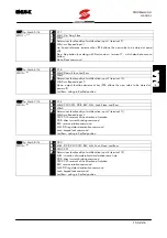
level = *.***%
F
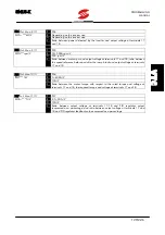
Determines the value for the activation of Open collector digital output for the
following settings: “Rmpout level”, “Reference level”, “Speed level”, “Forward
Running”, “Reverse Running”, “Tq out level”, “Current level”, “FB Max”, “FB Min”,
“Speedout O.K.”, “PID O.K.”.
P70 MDO. 12/19
P
P70
R
0÷200%
D
0 %
hyst. = *.*** %
F
When Open Collector digital output is set as “Rmpout Level”, “Reference
Level”, “Speed level”, “Forward Running”, “Reverse Running”, “Tq out level”,
“Current level”, “Speedout O.K.”, “PID O.K.”, “FB Max”, “FB Min”, this
parameter determines the digital output hysteresis range.
If the hysteresis is other than 0, the value set with P69 when the quantity set
with P60 increases determines the output commutation; when the output
decreases, commutation occurs when the value set in P69–P70 is reached
(Example: Set P60 = “Speed level”, P69 = 50%, P70 = 10%; the digital
output activation occurs when 50% of the preset maximum speed is
reached; deactivation occurs when 40% is reached).
If P70 = 0, commutation occurs when the value set in P69 is reached.
Open Collector MDO digital output set as “PID Max Out” and “PID Min
Out” determines the value for the digital output deactivation. The digital
output activates when PID regulator output (expressed as a percentage)
reaches the value set for P90 “PID Max Out” and P89 “PID Min Out”
respectively, and deactivates when the value set for P90 – P70 and P89 +
P70 is reached (see Figure 6.6 and Figure 6.7)
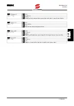
P71 RL1 13/19
P
P71
R
0 ÷200%
D
0 %
level = *.*** %
F
Determines the value for the activation of relay digital output RL1 for the following
settings: “Rmpout level”, “Reference level”, “Speed level”, “Forward Running”,
“Reverse Running”, “Tq out level”, “Current level”, “FB Max”, “FB Min”, “Speedout
O.K.” e “PID O.K.”.
V
T
C


