SINUS PENTA
REGENERATIVE
APPLICATION
105/
140
0
1
2
3
4
3.7.
ANALOG OUTPUTS MENU
3.7.1.
O
VERVIEW
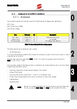
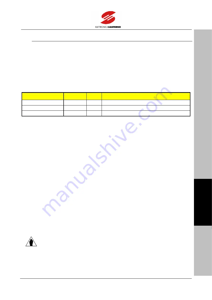
The variables assigned to the analog outputs are the following for the Regenerative applications:
AO1: Power
AO2: Output Current (RMS)
AO3: DC-bus Voltage
Item
Full-scale
Kri
Description
Drive power
1000.0 kW
10
Delivered active power
Output current
1000.0 A
10
Current RMS
DC-bus voltage
1000.0 V
10
DC voltage of the DC-bus
Table 11: Items allocated to the analog outputs.
The following items are mentioned for each variable:
-
the full-scale value;
the internal representation coefficient (Kri) required for scaling the maximum and minimum values in case of
programming via serial link;
Example: Max. value to be represented P179=100 A
→
the value to be programmed via serial link is
P179 = (100 A * Kri) = 1000.
The parameters relating to the following items are detailed in the Analog Outputs section in the Sinus Penta’s
Programming Instructions manual:
-
Operating modes of the analog outputs (voltage/current outputs);
-
Range of the variable;
-
Acquiring mode of the variable (“plus”, “minus” or as an absolute value);
-
Output values corresponding to the minimum and maximum value of the variable;
-
Possible offsets;
-
Applicable filter.
NOTE
Because the variables allocated to the analog outputs cannot be configured by
the user, parameters P177, P185, and P193 are not included in this menu.


