RIGENERATIVE
SINUS PENTA
APPLICATION
108/
140
0
1
2
3
4
0
1
2
3
4
3.9.
AUXILIARY DIGITAL OUTPUTS MENU
3.9.1.
O
VERVIEW
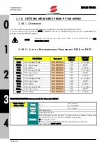
Auxiliary digital outputs XMDO1..6 can be programmed using the parameters contained in this menu.
This menu can be viewed only if parameter R023
≠
0 (see the EXPANSION BOARD CONFIGURATION MENU).
3.9.2.
L
IST OF
P
ROGRAMMABLE
P
ARAMETERS
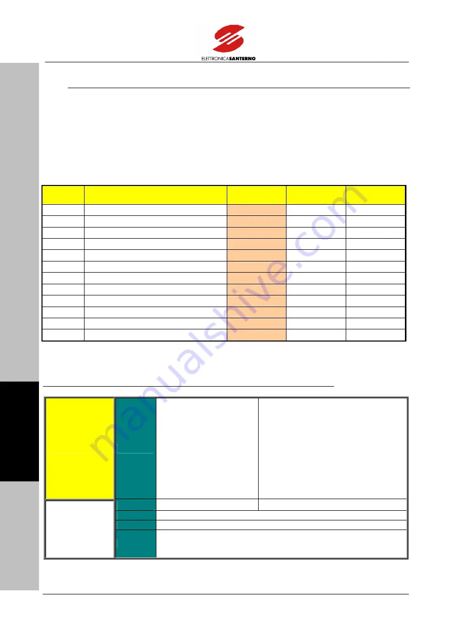
P582
TO
P593
Parameter
FUNCTION
User Level
MODBUS
Address
DEFAULT
VALUES
P582
XMDO1: Signal Selection
ENGINEERING 702 D0:
Disable
P583
XMDO1: Output Logic Level
ENGINEERING 703
1:
True
P584
XMDO2: Signal Selection
ENGINEERING 704 D0:
Disable
P585
XMDO2: Output Logic Level
ENGINEERING 705
1:
True
P586
XMDO3: Signal Selection
ENGINEERING 706 D0:
Disable
P587
XMDO3: Output Logic Level
ENGINEERING 707
1:
True
P588
XMDO4: Signal Selection
ENGINEERING 708 D0:
Disable
P589
XMDO4: Output Logic Level
ENGINEERING 709
1:
True
P590
XMDO5: Signal Selection
ENGINEERING 710 D0:
Disable
P591
XMDO5: Output Logic Level
ENGINEERING 711
1:
True
P592
XMDO6: Signal Selection
ENGINEERING 712 D0:
Disable
P593
XMDO6: Output Logic Level
ENGINEERING 713
1:
True
Table 14:
List of parameters P582 to P593.
P582/584/586/588/590/592 Variable Selected for Auxiliary Digital Outputs XMDO1/6
Range
0
÷
10
0: Synchronism OK
1: Run OK
2: Mains Fault
3: Drive OK
4: Alarm Tripped
5: W40 Fan Fault
6: Pre-charge OK
7: Command 1 from Fieldbus
8: Command 2 from Fieldbus
9: Command 3 from Fieldbus
10: Command 4 from Fieldbus
Default
3
3: Drive OK
Level
ENGINEERING
Address
702/704/706/708/710/712
Function
These parameters set the functions implemented from digital outputs
XMDOx. See
Table 15 for detailed functions.

