SINUS PENTA
REGENERATIVE
APPLICATION
115/
140
0
1
2
3
4
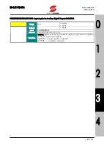
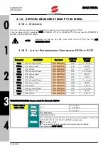
Note A)
To activate the drive control from fieldbus, set one of the control sources among C140
÷
C142 as Fieldbus.
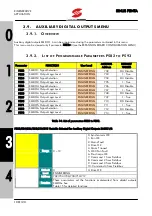
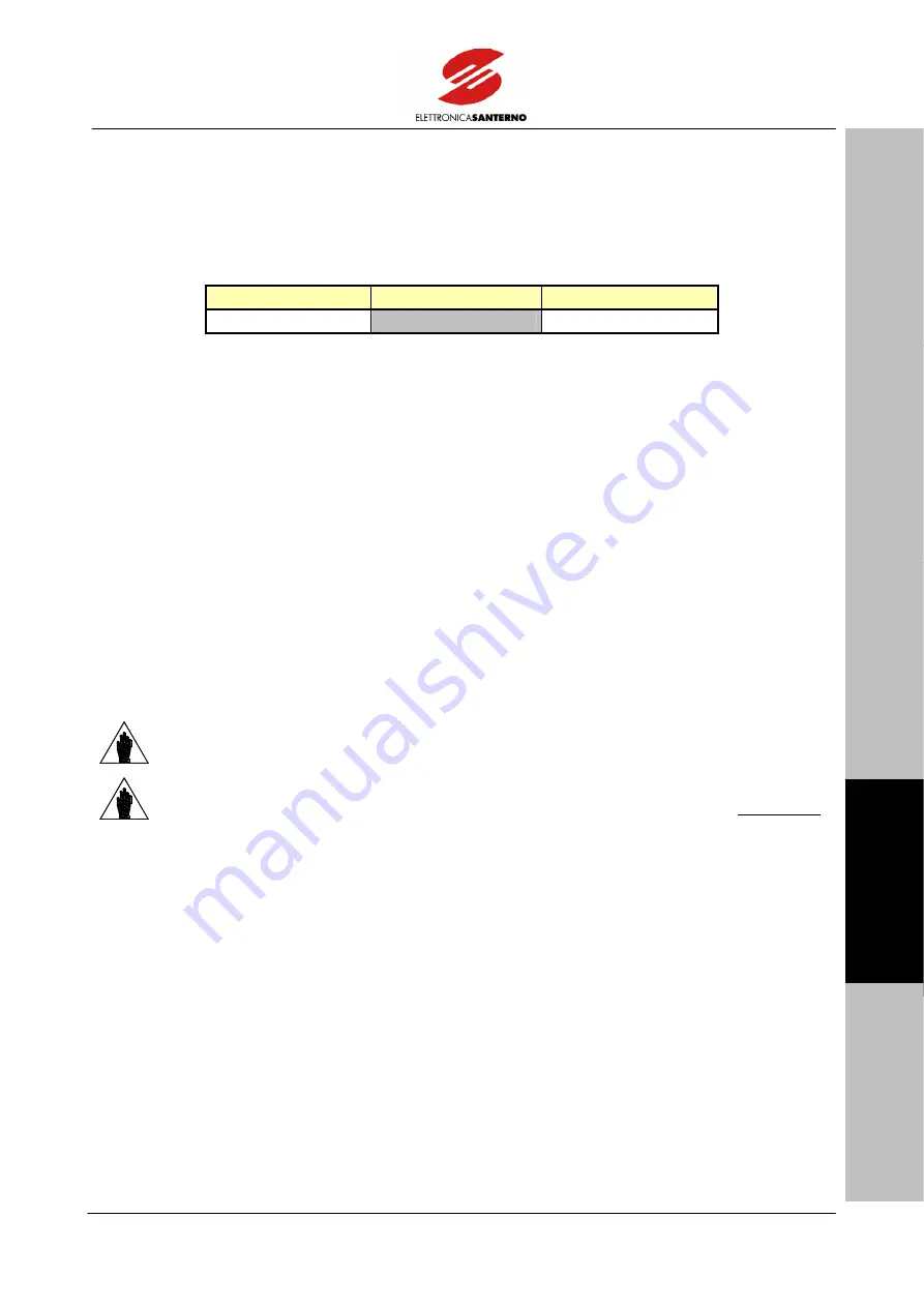
The simulated virtual terminal board is assigned to the low byte of the word:
bit 15
bit [14..8]
bit [7..0]
1
virtual terminal board
Bitmap:
0
→
MDI1
1
→
MDI2
(ENABLE)
2
→
MDI3
(RESET)
3
→
Not
Used
4
→
Not
Used
5
→
MDI6
6
→
MDI7
7
→
MDI8
The logic status of these bits is part of the overall status of the drive digital inputs (measure M032) along with
the other control sources if at least one among C140
÷
C142 is set as Fieldbus.
NOTE
Digital inputs MDI4 (external pre-charge closed signals) and MDI5 (filter capacitor
protection) are detected in the hardware drive terminal board only, as they are affected
by the hardware status of the cabinet where the drive is installed.
NOTE
Bit 15 must always be=1; this means that data exchanged from the master to the drive
is always consistent; as a result, the watchdog counter is kept reset (see “Alarm A070”).

