REGENERATIVE
SINUS PENTA
APPLICATION
36/
140
0
1
2
3
4
2.6.3.
S
IGNAL
W
IRING FOR THE
R
EGENERATIVE
D
RIVE
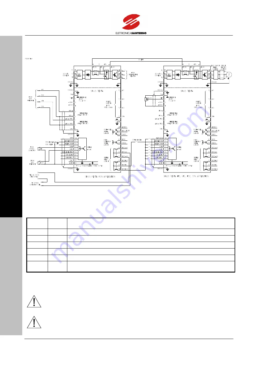
Figure 5: Signal wiring diagram for the regenerative drive.
Wiring for the regenerative drive powering a SINUS PENTA drive is shown in the wiring diagram above.
For the RGN application, the following analog and digital inputs/outputs are required:
Terminal
N.
Type of
I/O
Function
5 – 6
AIN1 Analog input for Vrs line voltage measured through the interface panel.
7 – 8
AIN2 Analog input for Vst line voltage measured through the interface panel.
17
MDI4 Digital input for TL1 bypass contactor auxiliary contact closure.
18
MDI5 Digital input for the state of the auxiliary contact in capacitor INT1 safety switch.
30 – 31 MDO3 NO relay output for TL1 bypass contactor coil command.
33 – 34 MDO4 NO relay output for regenerative drive “ON” to be series-connected to the motor drive
enabling chain.
Activate the ENABLE input (MDI2) to enable the regenerative drive; if it locks due to a fault, activate the RESET
input (MDI3) to reset the equipment.
CAUTION
Make sure that voltage and current in TL1 coil do not exceed MDO3-NO
contact ratings. If need be, install an additional external relay having greater
current ratings.
CAUTION
As shown in the wiring diagram, activate the MDO4-NO contact in the motor
drive enabling chain to prevent this from starting when the regenerative drive is
inactive.


