RIGENERATIVE
SINUS PENTA
APPLICATION
114/
140
0
1
2
3
4
0
1
2
3
4
3.11.3.
E
XCHANGED
P
ARAMETERS
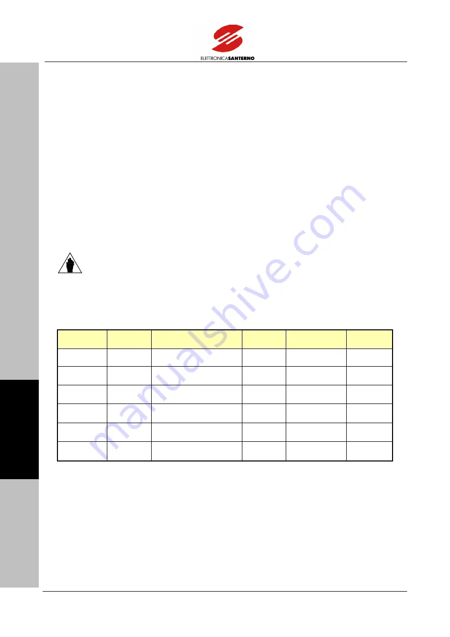
The tables below contain the Sinus Penta’s parameters that are exchanged via Fieldbus.
Each table includes:
1)
Position in the structure of exchanged parameters;
2)
The parameter number;
3)
Its description;
4)
Its setting range;
5)
Its unit of measure (which is also displayed on the display/keypad);
6)
The ratio between the value internal to the Sinus Penta (which is exchanged via Fieldbus) and the
hardware represented value (as displayed).
NOTE
Each parameter is exchanged as a 16-bit integer with a +/- sign (from –
32768 to +32767). The byte exchanging sequence follows the big-endian
rule (i.e. the most significant value is stored to the lowest address).
3.11.4.
F
ROM THE
M
ASTER TO THE
S
INUS
P
ENTA
1) Position
2) ID
3) Description
4) Range
5) Unit of
Measure
6) Ratio
1÷4 –
–
–
–
–
5
M035
Digital inputs from
FIELDBUS
–
Note A) –
6
Commands for digital
outputs from FIELDBUS
–
Note B)
–
7
AO1
Analog Output 1
controlled via FIELDBUS
+ 111
÷
+ 1889
Note C)
–
8
AO2
Analog Output 2
controlled via FIELDBUS
+ 111
÷
+ 1889
Note C)
–
9
AO3
Analog Output 3
controlled via FIELDBUS
+ 111
÷
+ 1889
Note C)
–

