SINUS PENTA
REGENERATIVE
APPLICATION
85/
140
0
1
2
3
4
3.2.7.
M
ENU N
.6
–
T
EMPERATURES FROM
PT100
This submenu can be viewed only if parameter R023=3:XMDO+PT100 or 4:XMDO+PT100+Pout (see the
EXPANSION BOARD CONFIGURATION MENU).
ES847 option board must be installed to view the measures in this submenu (please refer to the Sinus Penta’s
Installation Instructions manual).
3.2.8.
L
IST OF THE
O
PERATING
C
ONDITIONS OF THE
R
EGENERATIVE
S
INUS
P
ENTA
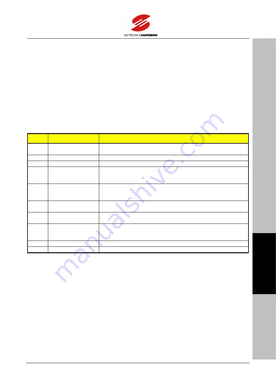
Each possible operating condition for the Regenerative Sinus Penta is given in the table below:
Value
Codification
Description
0 Pre-charge
Pre-charge stage; the drive is waiting for the DC-bus voltage to attain
Vdc_min.
1
Regen. Wait Ena.
Drive stopped waiting for the ENABLE command.
2
RUN P=****.*kW
Drive running; it is deli/–*****kW.
3
ALR VR MIN KO
The drive is disabled because the mains voltage has dropped below the
min. instantaneous voltage or the preset RMS (see the MAINS
PARAMETERS MENU).
4
ALR VR MAX KO
The drive is disabled because the mains voltage has exceeded the max.
instantaneous voltage or the preset RMS (see the MAINS PARAMETERS
5
ALR F.MAINS KO
The drive is disabled because the mains frequency is out of the preset
range (see the MAINS PARAMETERS MENU).
6
ALR PLL KO
The drive is disabled because the PLL is no longer synchronized with the
mains.
7
Cooling = ####.# s
COOLING: I*t alarm tripped because excessive current exceeding the
rated current was delivered for a too long time; the equipment is cooling
down.
8
ALARM
An alarm tripped.
9
Resetting
The drive is resetting the alarm tripped and is preparing to restart.
Table 7: Codification of the operating conditions of the Regenerative Sinus Penta.


