22
3.1 OPERATION
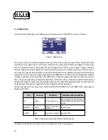
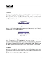
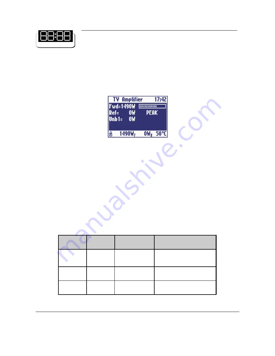
At startup, after initial image, the display shows the main screen with the RF powers as in Figure 1:
The user may turn on and off the amplifier by means of the switch on the front panel. The control board turns
on all the power supplies, the exciter (if any), and internal cooling fans. While the amplifier is working, the
micro-controller monitors continuously the most important parameters: power supply voltages, absorbed
currents, high power zone temperature, forward and reflected powers, unbalances (if any). Each measure is
associated to a maximum threshold beyond which the amplifier is immediately put in protection status by
turning off one or more power supply, depending on the failed block. In order to prevent a temporary problem
to trigger a definitive protection status, the failed block is turned on again, after some seconds, for up to five
times. If it goes beyond the protection threshold for more than five times, it is declared as FAILED and it will
no longer be turned on. In this case, the amplifier will have to be turned off manually by means of the switch on
the front panel, then turned on again after performing the needed maintenance.
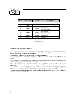
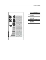
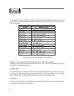
On the front panel there are also three LEDs labelled ON, REMOTE and ALARM. Their meanings are
explained in Table 1.
Figure 1: Main screen
Table 1: Meanings of the three LEDs on the front panel
1
Screenshots in this manual are indicative, so they can be different from those on your equipment.
LED
COLOUR
MEANING
MEANING WHEN BLINKING
ON
Green
The amplifier is on
The amplifier has been turned on
locally but it has been turned off by
remote
REMOTE
Yellow
Remote control i s
enabled
It never blinks
ALARM
Red
An alarm is present
It never blinks

