background image

Page 3

011822

1-888-651-3431

ASSEMBLY

Step 1: 

Unload all contents from box and check to make sure all parts and components are present.

Step 2:

  Thread knob into the 4 Bike Arm Bars (G). Set these parts aside. Repeat until all 4 Bike Arm 

Bars have in them. Set these parts to the side.

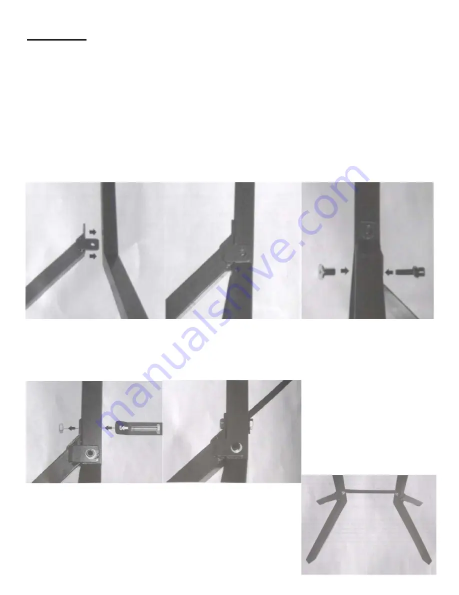
Step 3:

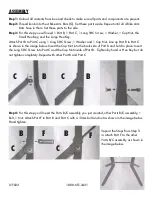
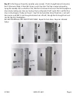
  For this step you will need 1 Part B, 1 Part C, 1 Long SHC Screw, 1 Washer, 1 Cap Nut, the 

Small Hex Key, and the Large Hex Key,

Attach Part B to Part C using 1 Long SHC Screw, 1 Washer and 1 Cap Nut. Line up Part B to Part C 
as shown in the image below. Insert the Cap Nut into the back side of Part B and hold in place. Insert 
the Long SHC Screw into Part C and the Cap Nut inside of Part B.  Tighten by hand or Hex Key but do 
not tighten completely. Repeat with other Part B and Part C

Step 4:

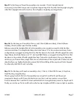
 For this step you‘ll need the Parts B/C assembly you just created, other Parts B/C assembly, 1 

Bolt, 1 Nut. Attach Part F to Part B and Part C with a 13mm bolt and nut as shown in the image below. 
Hand tighten. 

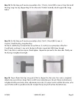
Repeat the Steps from Step 3 
to attach Part F to the other 
Parts B/C assembly as shown in 
the image below.

B

B

C

C

B

B

C

C

F

F

Summary of Contents for BR-STD

Page 1: ...ensure it is assembled properly and all Parts are in safe working order and free of defects Never modify this product in any way All circumstances cannot be addressed in these instructions Please use common sense and practice general safety measures when using this product Parts and or instructions are subject to change without notice Misuse or improper installation of this stand could result in s...

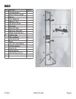
Page 2: ...r Bar 1 E Middle Logo Plate 1 F Top Bottom Connectors 2 G Bike Arm Bar 4 H Plastic Bike Cradle 1 I Rubber insert Bike Cradle 1 J Upright Internal Connectors 2 K Small Parts Bag 1 SHC screw 25mm 14 4mm head Cap Nut 14 Washer 6 13mm Hex Head Bolt 40mm 2 Small Hex Key 4mm 1 Large Hex Key 1 Knob for Bike Arm 4 Plastic End Caps for Part A 2 PARTS ...

Page 3: ...crew 1 Washer and 1 Cap Nut Line up Part B to Part C as shown in the image below Insert the Cap Nut into the back side of Part B and hold in place Insert the Long SHC Screw into Part C and the Cap Nut inside of Part B Tighten by hand or Hex Key but do not tighten completely Repeat with other Part B and Part C Step 4 For this step you ll need the Parts B C assembly you just created other Parts B C ...

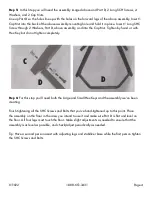
Page 4: ...ey but do not tighten completely Step 6 For this step you ll need both the Large and Small Hex Keys and the assembly we ve been creating Finish tightening all the SHC Screws and Bolts that you ve hand tightened up to this point Place the assembly on the floor in the area you intend to use it and make sure Part D is flat and level on the floor All four legs must touch the floor Make slight adjustme...

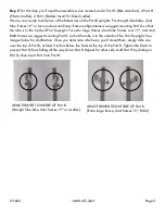
Page 5: ...a large frames slant tube frames over 19 and most BMX frames we suggest mounting Part G so that the tube is to the outside of the Part B upright See images below for clarification Once you determine which way you ll mount them simply slide one over the top of Part B at least 3 inches below the holes at the top of the Part B Tighten the Knob to prevent Part G from falling all the way down Part B Re...

Page 6: ...rt it into one of the Part B uprights as shown below making sure holes are lined up Next we ll position Part E next to Part J and Part B as shown in the diagram Finally we ll insert 1 Cap Nut into the bottom hole of B and into J and we ll then insert a small SHC Screw through the bottom hole of Part E through Part B through Part J and into the Cap Nut Hand tighten DO NOT TIGHTEN ALL THE WAY YET JU...

Page 7: ...rames slant tube frames over 19 and most BMX frames we suggest mounting Part G so that the tube is to the outside of Part B upright See Step 7 above for clarification Once you determine which way you ll mount them simply slide one on to the bottom of Part A end with 2 holes in it and about half way up Tighten the knob to prevent Part G from falling all the way down Part A Repeat for other side Add...

Page 8: ... holes of the Part F and Part A and insert 1 cap nut in the back of Part A Insert short SHC Screw through Part F into Part A and into cap nut Hand tighten Repeat the process for the other side Finally use the hex keys to tighten down tight Step 14 Pop in Plastic End Cap in top end of Part A Repeat for other side Your rack is completed Adjust arms up and down along Parts A and B to accommodate your...

Page 9: ...le for labor charges If the product does not meet specifications as depicted in the advertisement the Authorized Dealer will refund the full purchase price of the product Questions regarding the warranty on a specific product and warranty claims should be directed to the Authorized Dealer with whom the purchase transaction was made WARRANTY LIMITATIONS The above warranty does not apply to products...

Reviews: