Page 7
011822
1-888-651-3431
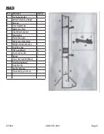
Step 9:
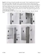
For this Step you’ll need the assembly we’ve created, 1 Part J ( Upright Internal
Connector), 2 short SHC Screws and 2 Cap Nuts. Repeat Step 8 for the other Part B upright using the
other Part J (Upright Internal Connector). Do not tighten completely, see image below.
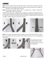
Step 10:
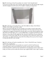
For this Step you’ll need the 2 Part A, and 2 Part G (Bike Arm Bars), 2 Part H (Plastic
Cradles), 2 Part I (rubber insert for bike cradles).
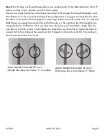
Before we mount the Uprights (Part A) to the assembly we’ve created, we need to slide the bike
arm bars onto them. For straight tube bikes, slant tube frames 19’’or less, and extraordinary frame
configurations we suggest mounting Part G so that the tube is to the inside of Part B upright. For extra
large frames, slant tube frames over 19’’, and most BMX frames, we suggest mounting Part G so that
the tube is to the outside of Part B upright (See Step 7 above for clarification). Once you determine
which way you‘ll mount them, simply slide one on to the bottom of Part A (end with 2 holes in it) and
about half way up. Tighten the knob to prevent Part G from falling all the way down Part A. Repeat
for other side, Add Part H and I as before.
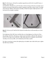
Step 11:
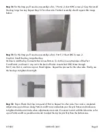
For this Step you’ll need our assembly so far, 1 Part A, 2 Short SHC Screws, 2 Cap Nuts,
Small Hex Key, Large Hex Key.
We are going to attach Part A to the assembly now using Part J and Part G just like we just
completed in Step 8 and 9. First we’ll slide Part A over Part J and into position on top of Part
B and in between Part J and Part G. Next we’ll attach Part A using the same process as Step 8 and 9.
Finally, we can line up Part A and B and use the hex key to tighten all SHC screws as tight as possible.


