


ISL55180 EVM Getting Started
Rev A04: 11/28/2012
Copyright
Elevate Semiconductor Corporation 2012
Page 20 of 20
4
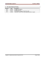
Document Revision History
Revision
Date
Description
A04
6/18/12
Updated several figures.
A03 2/27/12
Updated
document.
A02
1/27/10
Add loadboard changes and switcher section
A01
9/24/09
Initial Draft. ISL55180 R1 and Europa/Switcher Rev A support


