


Jupiter
EVM
Getting
Started
Rev
C01
:
05/17/2007
Copyright
Elevate Semiconductor 2012
Page 11 of 22
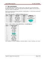
2.4.3 Ganging
(Merging) Configuration
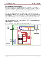
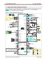
Figure 4 illustrates the recommended configuration for the ganging application. The Master (U1) is
configured in FV mode in Remote Sense while the Slave (U2) is configured in FI mode. The Master and
Slave both use the FORCE_B output pin which allows for internal alarm shut down. The Master and
Slave are connected to the TEST_NODE SMA via the loadboard relays and 2-pin jumpers (E7 for Master
and E5 for Slave). The E4 jumper must also be installed which provides the SENSE return path. The
GANG_0 node is used to provide the Master MI signal to the Slave device.
The loadboard SLAVE_EN (CBit4) control bit is used to completely isolate and/or connect the Slave
device supplies. The Slave device has the VCC and VCCO power pins tied together therefore the user
should tie the Master (main) VCC and VCCOUT together. The Slave shares the Master’s CPU_CK and
SDIO signals while the Master and Slave have dedicated STB and RESET signals. The Slave’s input
signals are tied low so there is no real-time control. The Slave’s Alarm is connected to an LED. The
Slave’s CBit outputs are not connected. The Slave’s MONITOR and TJ pins are accessible by the A/D
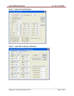
on the FVMI board; these results can be found in the
EVM Config->FVMI Measure
dialog box.
Note: The hardware supports Ganging via the FORCE_A pins; however, the software does not have a
default configuration for using FORCE_A.
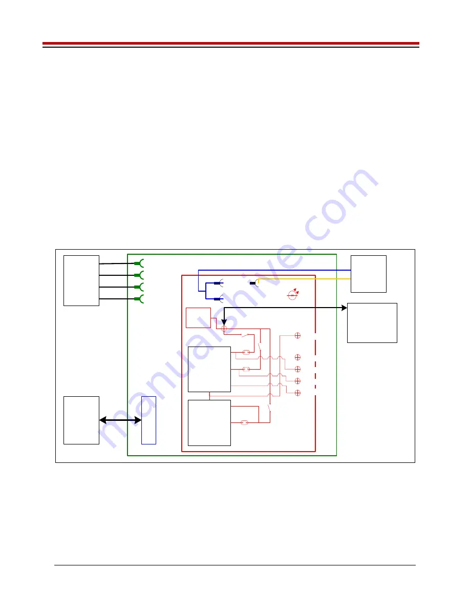
Figure 4: Jupiter EVM Ganging Configuration Simplified Block Diagram
Motherboard
Jupiter Load Board
PC
J2 (FVM
I)
Parallel
Cable
EVM
Power
Supply
Master
(U1)
DMM
or
Measurement
Unit
MONITOR
MONITOR
E4
SENSE
VCC
VCCOUT
VEE
+20V (BN1)
-15V (BN2)
+5V (BN3)
GND (BN4)
LEDs
FORCE_B
E7
SENSE
FORCE_B
TEST_NODE
Rnet
Cloads
GANG0
Slave
(U2)
MONITOR
SENSE
FORCE_B
GANG0
E5
GANG_0
FORCE_A
Jupiter
Power
Supply


