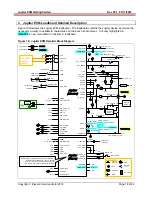
background image

Jupiter 

EVM 

Getting 

Started 

      Rev 

C01 

05/17/2007 


Copyright 

 Elevate Semiconductor 2012 


Page 19 of 22 

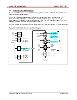
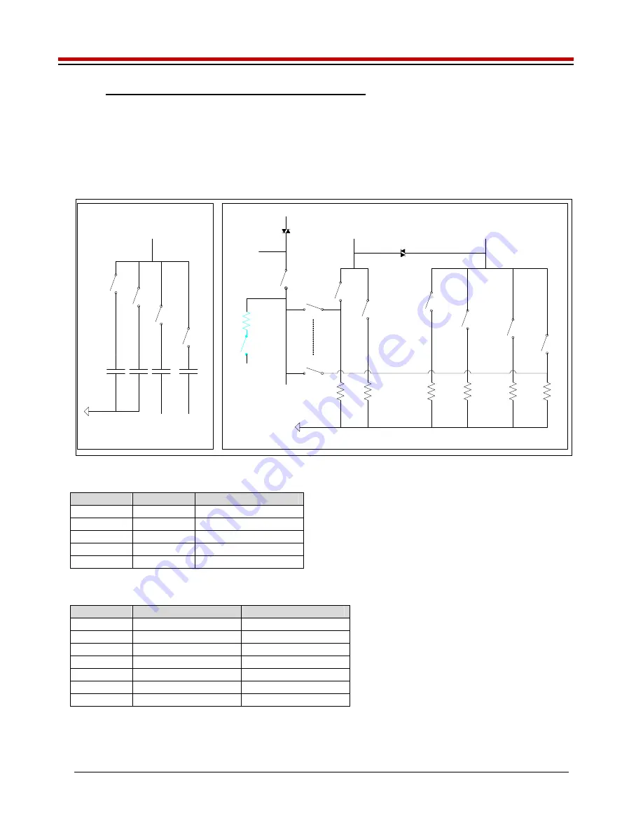
3.1  Capacitor and Resistor Network Definitions 

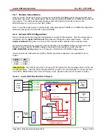
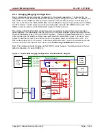
Figure 11 illustrates while Table 7 and Table 8 list the Jupiter EVM capacitor/resistor load network 
definitions.  Any capacitor combination can be switched in.  The software only allows a single resistor 
value to be switched in.  The CON_RNET_TN provides the ability to switch in a 1K resistor between 
FORCE_B (TestNode) and SENSE; this is used to create an IR drop in order to test/characterize the 
Kelvin Alarm threshold circuit. 
 

Figure 11:  Jupiter EVM Capacitor/Resistor Network Block Diagram 

Capacitor Network

Resistor Network

1.95

64K

125

15.8

LOAD_SEL5

LOAD_SEL4

LOAD_SEL3

LOAD_SEL0

LOAD_SENSE0

LOAD_SENSE5

SENSE

TEST_NODE

TestNode(p)

0.1u

CON_CAP1_TN

1u

CON_CAP2_TN

10u

CON_CAP3_TN

(CBit6)

VEE

A/D

TEST_NODE

1K

LOAD_SEL2

8K

LOAD_SEL1

47u

CON_CAP4_TN

(CBit3)

VEE

Rnet_Sense(p)

CON_RNET_SENSE

A/D

Sense(p)

1K

CON_RNET_TN

TestNode(p)


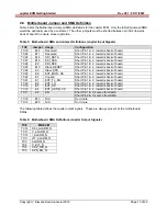
Table 7:  Capacitor Network Definitions 

CAP_# 

Code 

Capacitor Value 


-1 or 0 

Open All 

CAP1 1 

0.1uF 

CAP2 2 

1.0uF 

CAP3 4 

10uF 

CAP4 8 

47uF 


Table 8:  Resistor Network Definitions 

Code 

Current Range 

Resistor Value(s) 

-1 0  Open 

All 

0 15.625uA 

64K 

1 125uA 

8K 

2 1mA 

1K 

3 8mA 

125 

4 64mA 

15.8 

5 512mA 

1.95 


Summary of Contents for Jupiter

Page 1: ...Jupiter EVM Getting Started Rev C01 05 17 2007 Copyright Elevate Semiconductor 2012 Page 1 of 22 Jupiter EVM Getting Started Rev C01 05 17 2007 ...

Page 2: ...g the Elevate Semiconductor Program 6 1 3 5 Software Un Installation 6 2 Getting Started 7 2 1 Caution 7 2 2 Jupiter Loadboard Rev B versus Rev C 7 2 3 Quick Start Instructions 7 2 4 Default Configuration Setup Options 9 2 4 1 Remote Sense Option 10 2 4 2 General DPS Configurations 10 2 4 3 Ganging Merging Configuration 11 2 5 Jupiter Loadboard Jumper Definitions 12 2 6 Motherboard Jumper and SMA ...

Page 3: ...ral Register Dialog Box 17 Figure 10 Jupiter EVM Detailed Block Diagram 18 Figure 11 Jupiter EVM Capacitor Resistor Network Block Diagram 19 Figure 12 Controller Section Detailed Block Diagram 21 List of Tables Table 1 Jupiter EVM Contents 4 Table 2 Power Supply Requirements 5 Table 3 Jupiter Default Configuration Options 9 Table 4 Jupiter Loadboard Jumper Definitions 12 Table 5 Motherboard SMA an...

Page 4: ...instructions to install setup and operate the Jupiter EVM Refer to the Elevate Semiconductor EVM User s Guide for a detailed description of the EVM system 1 1 Unpacking Jupiter EVM Contents Please check the contents of the Jupiter EVM shipping carton to make sure you have received all of the items listed in Table 1 The system is already configured for the best setup except for connections to the p...

Page 5: ...software Table 2 Power Supply Requirements Module Supply Current Rating Motherboard 20V 1 0 5 A Motherboard 5V 0 5 A Motherboard 15V 0 5 A Jupiter VCC VCC_OUT 16V 2 3 2 0 A 4 Jupiter VEE 5V 2 3 2 0 A 4 Notes 1 The EVM 20V could also be used as the Jupiter VCC 2 Once the EVM operation is verified the customer can adjust the VCC VCCO VEE supplies 3 The Jupiter VCC VEE voltage should not exceed 34V R...

Page 6: ...ll be installed onto the desktop and in the Start Programs folder The Start Programs folder also contains links to the different product datasheets EVM User s Guide and documentation folder 1 3 2 Parallel Port ParPort2K Installation To install the ParPort2K parallel port driver run the setup exe from the ParPort2k sub directory after the main installation is complete and click the Install button F...

Page 7: ...ils Refer to previous document revisions when using the Rev B loadboard The software supports both loadboard revisions 2 3 Quick Start Instructions 1 Disable external power supply 2 Connect the power supplies cables not provided from the power supply to the Elevate Semiconductor EVM Motherboard and Jupiter loadboard refer to Figure 3 3 Connect the parallel cable provided from the PC to J2 on the O...

Page 8: ...ge 8 of 22 Figure 2 Expected Current Readings The Reset System will put the EVM and Jupiter device into the default state The Reset System should be issued whenever the power supply is powered OFF then ON The Reset System is automatically performed when the program is initially launched ...

Page 9: ...led Connect DPS output to TEST_NODE via FORCE_B VFORCE2 1 5V VFORCE 0V Default applies to all software configurations Loadboard Jumpers E2 E4 and E7 are installed Jupiter CPU En 1 and Local Sense 1 Jupiter Monitor Enabled Sel MV MV Jupiter Iclamps 700mA Vclamps 14V 2V but disabled Jupiter COMP_A COMP_B and External CAP_SR connected and SR Adj 15 FORCE A default configuration Loadboard FORCE_A is c...

Page 10: ...x to connect to the on board resistor network and or capacitive load For the External DAC mode jumper E1 must be installed The VFORCE2 voltage is connected to the Gang2 V input and the VFORCE voltage is connected to the Gang3 V input Use the EVM FVMI DPS Config dialog box to change the VFORCE and VFORCE2 voltage values If using an external measurement unit MU the MU should be configured in the opp...

Page 11: ... VCCO power pins tied together therefore the user should tie the Master main VCC and VCCOUT together The Slave shares the Master s CPU_CK and SDIO signals while the Master and Slave have dedicated STB and RESET signals The Slave s input signals are tied low so there is no real time control The Slave s Alarm is connected to an LED The Slave s CBit outputs are not connected The Slave s MONITOR and T...

Page 12: ... different feedback options Always ensure there is a proper feedback so the DPS op amp isn t open loop Table 4 Jupiter Loadboard Jumper Definitions Jumper Description Default Configuration E1 Connect VFORCE Installed for ExtDAC E2 FORCE_A to TEST_NODE Installed E3 FORCE_A to SENSE Open E4 SENSE to TEST_NODE Installed E5 Slave FORCE_B to TEST_NODE Installed for Ganging E7 FORCE_B to TEST_NODE Insta...

Page 13: ...d TC26 E2 SDI_RCK Short Pin 1 2 towards back of board TC25 E10 Slave RESET Short Pin 1 2 towards back of board TC24 E9 Slave STB Short Pin 1 2 towards back of board TC23 E8 EXT_MON_OE Short Pin 1 2 towards back of board TC22 E7 Unused Short Pin 1 2 towards back of board TC21 E1 EXT_TJ_EN Short Pin 1 2 towards back of board TC20 E6 EXT_LD Short Pin 1 2 towards back of board TC19 E5 EXT_UD Short Pin...

Page 14: ...cess to the Jupiter dialog boxes For each Jupiter register there is a control field allowing the customer to have full control over the Jupiter device These screen shots show the default FV out FORCE B with Alarms configuration There are separate menu and dialog boxes for the Master and Slave device The Slave dialog boxes are only available if the Slave is detected Figure 5 Device Config Menu Opti...

Page 15: ...Jupiter EVM Getting Started Rev C01 05 17 2007 Copyright Elevate Semiconductor 2012 Page 15 of 22 Figure 6 Jupiter Configuration Dialog Box ...

Page 16: ...Jupiter EVM Getting Started Rev C01 05 17 2007 Copyright Elevate Semiconductor 2012 Page 16 of 22 Figure 7 Jupiter DC Levels Dialog Box Figure 8 Jupiter DAC Configuration Dialog Box ...

Page 17: ...Jupiter EVM Getting Started Rev C01 05 17 2007 Copyright Elevate Semiconductor 2012 Page 17 of 22 Figure 9 Jupiter Central Register Dialog Box ...

Page 18: ...T_ADDR_CK TC18 EXT_U D TC19 A D E4 FORCE_B CON_SENSE_TN CON_FB_TN CAP_BP CAP_AP E3 E8 TESTNODE p A D DPS_EN TC6 CAP_DIS TC8 C_BIT Tj CON_TJ_TN A D Jupiter Slave CLK SDIO STB RESET 3 TC_10 2 24 TC_25 VCC VCCOUT VEE VDD VCC VEE VDD DUT_GND GND VREF VREF GANG 3 0 4 E11 FORCE_A SENSE CON_SLAVE_TN E5 FORCE_B CAP_A BP CAP_A BN x2 x2 TEST_NODE All Slave Gang supplies and input output signals are isolated...

Page 19: ...acterize the Kelvin Alarm threshold circuit Figure 11 Jupiter EVM Capacitor Resistor Network Block Diagram Capacitor Network Resistor Network 1 95 64K 125 15 8 LOAD_SEL5 LOAD_SEL4 LOAD_SEL3 LOAD_SEL0 LOAD_SENSE0 LOAD_SENSE5 SENSE TEST_NODE TestNode p 0 1u CON_CAP1_TN 1u CON_CAP2_TN 10u CON_CAP3_TN CBit6 VEE A D TEST_NODE 1K LOAD_SEL2 8K LOAD_SEL1 47u CON_CAP4_TN CBit3 VEE Rnet_Sense p CON_RNET_SEN...

Page 20: ... VINPOS A VINNEG A Mapping Addr VINP VINPOS A VINN VINNEG A 7 VINP8 Reserved VINN8 VREF Div Sense 8 VINP9 GANG_MON p VINN9 TJ Master 9 VINP10 EXT_SENSE p VINN10 LB_AMUX see below 10 VINP11 MONITOR p VINN11 TJ Slave 11 VINP12 SENSE p VINN12 MON_REF p 12 VINP13 LB_AMUX see below VINN13 GANG3 p 13 VINP14 TEST_NODE p VINN14 REXT Table 10 Jupiter Loadboard Analog Mux Definitions LB_AMUX Mapping Addr Lo...

Page 21: ...relays the C Bits originate from the Octal FVMI board Figure 12 Controller Section Detailed Block Diagram Latch I 4 AMUX Address 4 DUT_GND_SEL1 DUT_GND_SEL2 REXT_SEL DUT_VREF_SEL Latch J 8 Latch K 8 CON_CAP1_TN SPARE CON_SENSE_TN CON_FA_TN CON_CAP2_TN CON_EF_TN CON_FB_TN CON_ES_TN EEPROM 1K x 16 bit LPORT1_ OUT 4 2 3 LPORT1_ IN2 TC_29 26 2 TC_28 Latch L 6 TestNode p CON_GANG_TN 1 0 CON_MON_REF_TN ...

Page 22: ...d Rev A support B01 Dec 13 2005 Overhauled for Jupiter Rev 4 and Loadboard Rev B support B02 May 31 2006 Jupiter R8 support Added ForceA B with Alarms option B03 Nov 24 2006 Jupiter Slave support Added screen shots for all dialog boxes Remove E3 E8 jumpers from Figure 3 was misleading Updated Table 4 E9 is Installed E10 is left Open C01 May 17 2007 Jupiter R10 support and Loadboard Rev C support ...

Reviews: