


Jupiter
EVM
Getting
Started
Rev
C01
:
05/17/2007
Copyright
Elevate Semiconductor 2012
Page 21 of 22
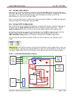
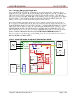
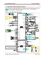
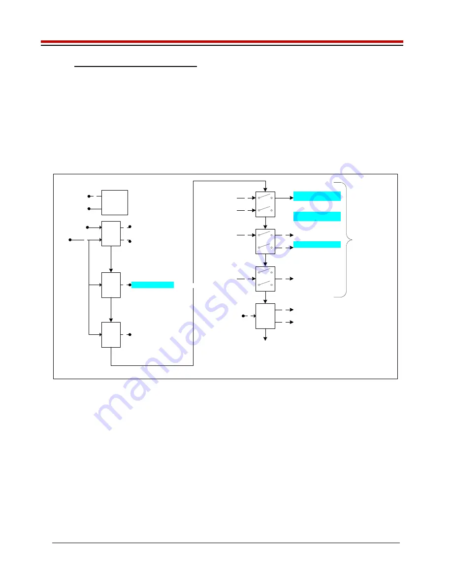
3.3 Jupiter Loadboard Controller
The Jupiter loadboard contains seven 8-bit latches (registers) and a 16K EEPROM. Figure 12 illustrates
the Jupiter EVM controller section.
The latches are daisy chained together using the SDI_SCK/RCK/CS signals originating from the
Motherboard. The EEPROM is controlled by the LPORT1_OUT[4:2] signals originating from the
motherboard. The loadboard latches are labeled STB_I to STB_O. This was named as an extension to
the REG_A to REG_H Octal FVMI / Motherboard registers.
The Cbit1 to CBit7 are also used to control various relays, the C-Bits originate from the Octal FVMI board.
Figure 12: Controller Section Detailed Block Diagram
Latch
I
4
AMUX Address
4
DUT_GND_SEL1
DUT_GND_SEL2
REXT_SEL
DUT_VREF_SEL
Latch
J
8
Latch
K
8
CON_CAP1_TN
SPARE
CON_SENSE_TN
CON_FA_TN
CON_CAP2_TN
CON_EF_TN
CON_FB_TN
CON_ES_TN
EEPROM
1K x 16-bit
LPORT1_
OUT[4:2]
3
LPORT1_
IN2
TC_29/26
2
TC_28
Latch L
6
TestNode(p)
CON_GANG_TN[1:0]
CON_MON_REF_TN
SPARE
Latch M
6
SENSE(p)
6
LOAD_SENSE[5:0]
Latch N
8
8
Latch
0
TC_29/26
2
SER_DATA
Swi
tc
hes
al
so
inc
lud
e 8
-bi
t l
at
ch
TC_5
TC_6
TC8
TC12
TC9
TC13
TC14
TC11
DPS_EN_N
CAP_DIS_N
C_BIT_N
I_ALARM_N
ALARM_N
V_ALARM_N
KEL_ALARM_N
OT_ALARM_N
2
CON_RNET_TN
6
2
LOAD_SEL[5:0]
SPARE (2)
SER_DATA2
(Serial Readback)
CON_RNET_SENSE
GANG2_SEL
RESET_SOT
RB_MUX[1:0]
GANG3_SEL
SPARE
CON_VFORCE_EF
CON_TN_DIV
2
VFORCE
VFORCE2
CON_GANG2_VF2
CON_GANG3_VF
CON_MON_TN
CON_TJ_TN


