background image

ELECTRICAL CONNECTION 

The appliance is fitted with an approved 15 Amp flexible cord and plug which must be connected to a 
correctly earthed socket outlet. The manufacturer is not liable for any direct or indirect damage caused by 
faulty installation or connection. It is therefore necessary that all installation and connection operations are 
carried out by qualified personnel complying with the local and general regulations in force. 

The wire section on the cable must not be less 
Than1.5mm (3

×

1.5cable).Use only the special 

cables available at our service centers.

CONNECTION OF THE FEEDING CABLE TO THE MAINS 
Connect the feeding cable to a plug suitable for the load indicated on the rating plate of the product. In case of 
a direct connection to the mains (cable without plug), it is necessary to insert a suitable omnipolar switch 
before the appliance, with minimum opening between contacts of 3 mm (the grounding wire should not be 
interrupted by the switch). 
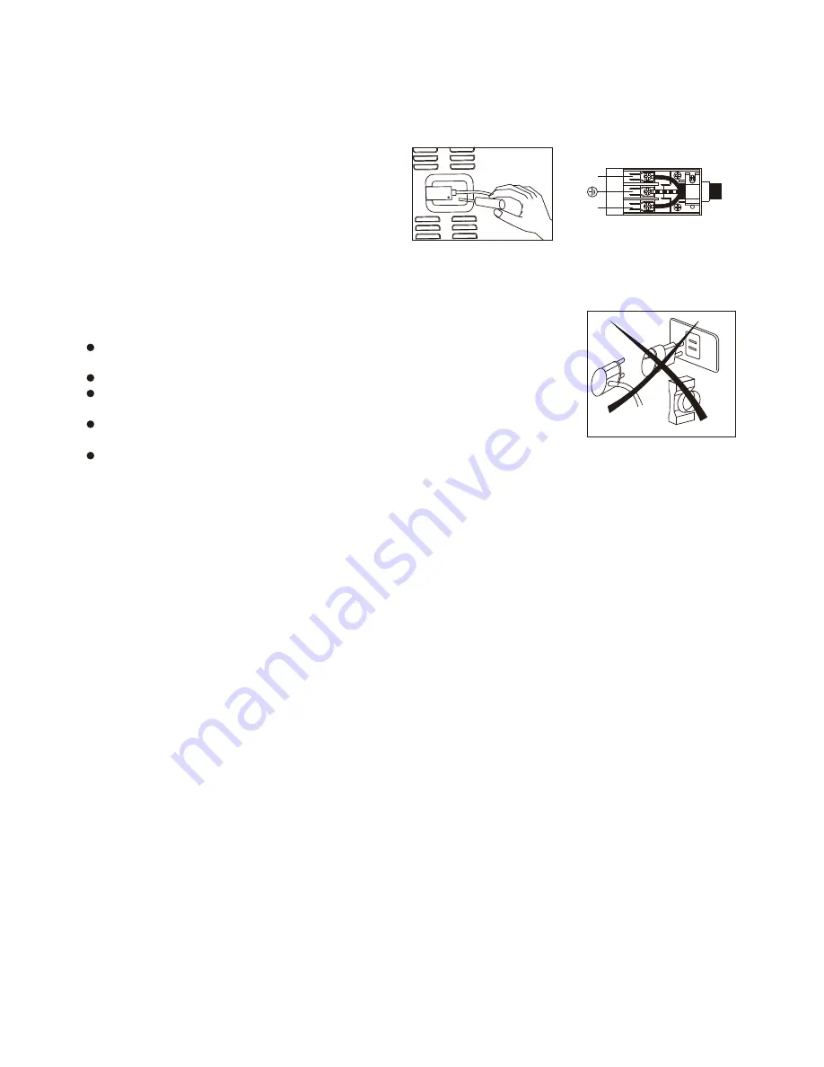
Before connecting to the mains, make sure that: 
       The electrical counter, the safety valve, the feeding line and the socket are ade
       quate towithstand the maximum load required(see rating plate). 

The supply system is regularly grounded, according to the regulations in force. 
The socket or the omnipolar switch can easily be reached after the installation 

       of the oven. 

After carrying out the connection to the mains, check that the supplying cable 

       does not come into contact with parts subject to heating. 

Never use reductions, shunts, adaptors which can cause overheating or burning. 

The manufacturer is not liable for any direct or indirect damage caused by faulty installation or connection. It 
is therefore necessary that all installation and connection operations are carried out by qualified personnel 
complying with the local and general regulations in force. 

Electrical features 
Oven light                                                                                     2

×

W                                           

Upper heating element                                                                 2200W                                  
Bottom heating element                                                               1800W                            
Grill heating element                                                                    2900W                    
Circular heating element                                                        2

×

1600W      

Ventilator  motor                                                                          2

×

30W      

Cooling fan                                                                                         11W
This appliance shall be installed only by authorised persons and in accordance with the manufacturer's 
installation 

instructions, 

local  gas  fitting  regulations, 

municipal 

building  codes,  electrical 

wiring 

regulations, local water supply regulations. 

Ventilation 
In general, the appliance should have adequate ventilation for complete combustion of gas, proper flueing 
and to maintain temperature of immediate surroundings within safe limits. 

Combustible Surfaces 
Any adjoining wall surface situated within 200mm from the edge of any hob burner must be a suitable non-
combustible material for a height of 150mm for the entire length of the hob. Any combustible construction 
above the hotplate must be at least 600mm above the top of the burner and no construction shall be within 
450mm above the top of the burner. Zero clearance is permitted on side and rear adjoining surfaces below the 
hob. 
Gas connection 
The appliance must be connected to the gas supply or the cylinder according to the specifications of the 
standards and after checking that it is adjusted for the type of gas available. 
The gas connection is male 1/2

"

 BSP and is situated 55mm from the right and 560mm from the floor. 

There are two ways to carry out 

the connection to the main gas line: 
A. The Cooker can be connected with the cuprum material . Loosen the tie-in down and connect one terminal 
of the pipe with the gas elbow 

25

Spit motor                                                                                     4W                                                    

It's 

necessity of changing the flexible tube whenthe national conditions require it.

2

L

N

6

Summary of Contents for BUGEG95WCD

Page 1: ...FREESTANDING COOKERS MANUAL FREESTANDING COOKERS INSTALLATION AND OPERATIONAL INSTRUCTIONS FOR BUGEG95WCD ...

Page 2: ...l enhance your kitchen such as cook tops Range hoods built in hobs built in ceramic hobs and built in ovens These are models to complement your new oven We make every effort to ensure that our products meet all your requirements Our customer relations department is at your disposal to answer all your questions and to listen to all your suggestions Please complete the warranty section of this manua...

Page 3: ...inimum flame Burner and injector characteristic table Instructions for use Description of the main parts of the appliance Ignition and operation of the burners Advice on the use of gas burners Oven function Electronic programmer Maintenance and cleaning CAUTIONS Instructions for cooking pag 7 pag 7 pag 6 pag 6 pag 5 pag 3 4 pag 17 pag 15 pag 13 pag 9 pag 10 pag 11 pag 12 pag 11 ...

Page 4: ...ted keeping the natural ventilation outlets open or installing a ventilation hood with rain duct l If the mains of a burner is turned off accidentally turn off the control knob Only light the oven again after waiting at least a Minute Before using the oven we suggest to l Remove all the special film covering the oven door glass when provided l Heat the empty oven at max Temperature for 45 minutes ...

Page 5: ...ty Children should be supervised to ensure that they do not play with the appliance l If the supply cord is damaged it must be replaced by the manufacturer its service agent or similarly qualified persons in order to avoid a hazard In the event of burner flames being accidentally extinguished turn off the burner control and do not attempt to re ignite the burner for at least 1 min l Note These ins...

Page 6: ...s of the cooker The screws should be fitted as follows Position the oven between the cupboards in it s final position then mark the location of the pilot hole inside the cupboard Refer to the diagram below for the location of the pilot hole Use 3 5mm diameter drill bit to drill the pilot hole through the cupboard and both sides of the cooker Before drilling check your measurements to ensure the pi...

Page 7: ...refore necessary that all installation and connection operations are carried out by qualified personnel complying with the local and general regulations in force Electrical features Oven light 2 W Upper heating element 2200W Bottom heating element 1800W Grill heating element 2900W Circular heating element 2 1600W Ventilator motor 2 30W Cooling fan 11W This appliance shall be installed only by auth...

Page 8: ...s have been carried out refer to the authorised service provider in your area Adaptation to different types of gas To adapt the appliance to a gas different from that for which it was set up see gas type label inside the warming compartment door proceed as follows remove the grids remove the burners caps and burner heads with a 7 mm socket spanner unscrew and remove the injectors replace the injec...

Page 9: ...the by pass screw located above left of the gas valve shaft as shown right Turn gently the by pass screw clockwise to the end l l LPG TO NG Use a thin blade screwdriver to turn the by pass screw located above left of the gas valve shaft as shown right Turn gently the by pass screw clockwise to the end completely then turn it anti clockwise 1 turn for the Triple ring 7 8 turn for the Fish 3 4 turn ...

Page 10: ...5 125 3 0 214 0 95 F4 0 50 0 85 0 65 0 85 G31 37mbar Input Input G30 29mbar G30 G31 kw g h 3 7 269 1 0 72 7 2 8 203 1 75 127 3 0 218 Main Injector mm 0 95 F4 0 50 0 85 0 65 0 85 Input G30 G30 I3 28 30 37 Burner Consumption Natural gas By pass mm kw Main Injector mm 1 2 4 3 5 Test point pressure G20 20mbar Rapid Semi rapid Auxiliary Fish BBQ Triple ring 0 44 0 34 0 64 0 29 0 64 3 7 1 0 2 8 1 75 3 0...

Page 11: ...ch it is installed Ensure that the kitchen is well ventilated keep natural ventilation holes open or install a mechanical ventilation device mechanical extractor hood 3 Prolonged intensive use of the appliance may call for additional ventilation for example opening of a window or more effective ventilation for example increasing the level of mechanical ventilation where present e g DO not use the ...

Page 12: ...ded intervenes in case of accidental flame failure blocking the gas delivery e g air draughts spillage of liquids etc In any case the ignition device must not be actuated for longer than 15 seconds Should the ignition manoeuvre fail or should the burner be accidentally turned off immediately close the actuation knob and repeat the ignition after one minute at least Once the ignition has taken plac...

Page 13: ...in the oven DELICATE COOKING THERMOSTAT SELECTOR SWITCH FROM 60 TO MAX Ideal for pastries and cakes with wet covering and little sugar and damp desserts in moulds Excellent results can also be achieved in completing cooking at the bottom and with dishes requiring heat in the Lower area in particular The plate is best inserted at bottom level TOP OVEN COOKING THERMOSTAT SELECTOR SWITCH FROM 60 TO M...

Page 14: ...will flash After the roast is finished the roast operation process will be shut automatically Then AUTO flashing the alarm Rings The ring will stop by pressing the button B Set the time of ending 23hours 59minutes maximum Press the button to set the time of ending The oven starts immediately and AUTO will flash When the set time of ending comes the roast operation process will be shut automaticall...

Page 15: ...3 14 ...

Page 16: ...he thermostat estinguishes Grill cooking Delete pre heat the oven for about 5 minutes During grill operation the heat comes from above it is based on the infrared radiation and is fit for low thickness meat and for toasts The meat and the fish to be grilled are to be slightly oiled and always placed on the grate this is to be arranged on the nearest or on the farthest guide from the grill element ...

Page 17: ... to dimensions 150 170 2 3 Fish 20 25 25 30 20 25 190 210 190 210 190 220 2 2 2 Time in minutes Level from below First courses Lasagne Oven baked pasta Creole rice Temperature Fan forced cooking First courses Lasagne oven baked pasta 210 230 210 230 30 40 Roast fish 170 200 According to dimensions MEAT Roast veal Roast beef Roast pork Chicken Duck Goose turkey Rabbit Leg of lamb 175 200 210 240 17...

Page 18: ... to turn contact a qualified engineer to lubricate the taps Contact a qualified engineer to deal with any other problems which may arise during use To keep the characteristics of brightness of the enamelled parts for a long time it is necessary to clean the oven after each cooking Once the oven is cold you will be able to easily remove the fat deposits by means of a sponge or a cloth damp with war...

Page 19: ... PADS ITS PURPOSE IS BOTH PROVIDING BETTER STABILITY AND AVOIDING SCRATCHES ON THE PLANE SURFACES DURING USAGE Cleaning the oven door Unhooking the doors For a more thorough clean you have to remove the oven door Choose the removal and assemble method according to different structure of oven door purchased Proceed as follows Open the door fully Lift up and turn the small levers located on the two ...

Reviews: