background image


43 


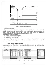
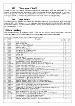
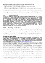
  Time of each tariff change must be later then time of previous tariff change; 

  If  no  tariff  changes  are  described  in  day  tariff  program,  all  the  data  are  assigned  to 

emergency tariff (refer to chapter 10.5). 


10.2  Week tariff program 

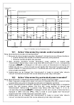
Week  tariff  program  (see  Table  10-2)  indicates  what  day  tariff  program  becomes  active  on 
separate  days  and  special  days.  Up  to  12  week  tariff  programs  can  be  created  in  meter  G1B. 
Table 10-2 introduces an example of week tariff programs (WP). 


Table 10-2 Example of week profiles 

Day tariff 

program 

number 

Monday 

Tuesday 

Wednesday 

Thursday 

Friday 

Saturday 

Sunday 

Special days 

1

st

 WP 

2

nd

 WP 

3

rd

 WP 


n

th

 WP 


10.3  Tariff seasons 

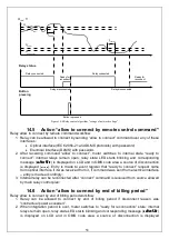
Tariff seasons (see Table 10-3) allow activating the specified week tariff program on the specified 
date (MM.dd). A year can be divided in up to 12 tariff seasons. 


Table 10-3 List of tariff seasons 

Season number 

Season start date 

Assigned week tariff program 

01.01 

02.01 

03.01 


12.01 


10.4  List of special days 

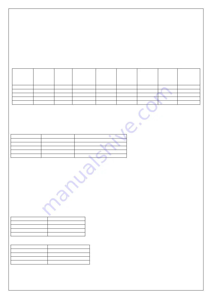
There are two lists of special days in the meter. One list is composed of permanent special days 
(the same date each year) and the other list contains leap-special-days (different date each year). 
Both  lists  in  total  may  contain  up  to  128  special  days.  Meter  LCD  displays  all  special  days, 
furthermore,  they  may  be  reviewed  in  a  computer  when  meter  parameters  are  read  via 
communication interface. 
When a new day begins, the meter addresses to the special days list and checks whether that day 
is in that list. If the day is specified in either special day list, the tariff module activates day profile 
for special day. 


Table 10-4 Special days list 

Special day number 

Special day (MM/dd) 

01/01 


12/25 

n* 

12/26 


Table 10-5 Leap-special-days list 

Special day number 

Special day (yy/MM/dd) 

09/04/13 

10/04/05 


m* 

23/04/10 

*the following condition must be followed - (n + m) ≤ 128 


Summary of Contents for G1B Series

Page 1: ...Static electricity meter GAMA 100 G1B xxx User manual Version 2 3b G1BEN23b ELGAMA ELEKTRONIKA Ltd Lithuania 2016...

Page 2: ......

Page 3: ...ELGAMA ELEKTRONIKA Static electricity meter GAMA 100 G1B xxx USER MANUAL ELGAMA ELEKTRONIKA Ltd 2 Visori str LT 08300 Vilnius Ph 370 5 2375000 Fax 370 5 2375020 E mail info elgama eu...

Page 4: ...irmware upgrade functionality was added 2 1 2014 04 29 Description of internal PRIME PLC modem modification H2 and firmware upgrade functionality was added 2 2 2015 03 04 Tariff program update LCD lis...

Page 5: ...Construction 16 5 1 Case 16 5 2 Nameplate 16 5 3 Terminal block 17 5 4 Operation principle 18 5 4 1 Measurement module 18 5 4 2 Signal conversion 18 5 4 3 Micro controller 18 5 4 4 Non volatile memory...

Page 6: ...41 9 4 Under voltage monitor 41 10 Tariff program 42 10 1 Day tariff programs 42 10 2 Week tariff program 43 10 3 Tariff seasons 43 10 4 List of special days 43 10 5 Emergency tariff 44 10 6 Tariff t...

Page 7: ...connect by end of event 59 14 8 Action connect by Menu button 59 14 9 Action connect by the mains switch of the internal electrical installation 59 15 Installation 60 Annex A Dimensions of the meter...

Page 8: ...alling parameterization and verification can be performed only by authorized organizations that have qualified technicians Only qualified persons should install meters 2 Meter s connection or disconne...

Page 9: ...check whether inputs are connected properly to terminal block 4 If meter calendar season season time name or valid tariff time zone does not correspond to real situation meter s parameterization data...

Page 10: ...meters for active energy classes 1 and 2 IEC 62053 23 2003 Electricity metering equipment a c Static meters for reactive energy classes 2 and 3 IEC 62052 11 2003 Electricity metering equipment a c Gen...

Page 11: ...able 3 2 Technical specifications Accuracy class Active energy measurement B EN 50470 3 1 0 IEC 62053 21 Reactive energy measurement 2 0 IEC 62053 23 Reference voltage Un V See Table 4 2 Operating vol...

Page 12: ...meters with supercapacitor 40 T 70 C 3K7 25 T 70 C Storage transportation 40 T 70 C Mass kg 0 9 Dimensions mm with usual terminal cover with special terminal cover for GSM GPRS modem 180 x 130 x 65 s...

Page 13: ...tuned to 50 Hz narrow band Total Harmonic Distortion THD for current and voltage is calculated by formulas 2 2 2 NB NB WB I I I I THD 2 2 2 NB NB WB U U U U THD IWB RMS value of current measured in w...

Page 14: ...attery for old battery s replacement Disconnect old battery s connector remove the battery Place new battery into old one s location and connect plug to the corresponding meter socket Put in silicone...

Page 15: ...ordering code and are listed in Table 4 10 Optional LCD display supports indication of up to 6 six tariffs Extended LCD displays OBIS code by means of 6 symbols while default LCD and optional LCD poss...

Page 16: ...e possibility to touch the meter terminals with sealing wire while sealing the terminal cover is prevented Figure See Figure 5 1 presents meter exterior parts and allotment of control elements For cas...

Page 17: ...mark number of the EC design examination certificate 13 The conformity marking CE and M number of notified body 5 Reference voltage current measuring range reference frequency 14 The class index of th...

Page 18: ...rter Digital signal processor DSP calculates average power values P t and Q t as well as instantaneous RMS values of current and voltage Furthermore DSP outputs values of RMS current in neutral and el...

Page 19: ...voltage of battery is to low and warns when battery has to be replaced 2 Index field Identifies measured data code OBIS code Explanation of OBIS codes for basic data can be printed on meter s namepla...

Page 20: ...rinted on meter s nameplate 3 Communication indicator Indicates when communication operates via optical or electrical communication interface 4 Main value field Shows the measured value up to 8 digit...

Page 21: ...riff field T1 T2 T3 T4 T5 T6 Shows current energy tariff only one segment is turned on Lit segment indicates active energy tariff blinking segment indicates active emergency tariff for energy 6 Billin...

Page 22: ...ward MM00 hh Clock is adjusted for summer time on the last Sunday of a specified month on the time specified by winding the clock 1 hour forward Clock is adjusted for standard time on the last Sunday...

Page 23: ...d voltage circuits are connected permanently Figure 5 8 Sliding voltage link connected 6 Communication The meter supports two way communication via various interfaces data reading at the request as we...

Page 24: ...2 as well as fixed to DIN rail separately For more information please refer to modem s instruction Meter is equipped with RJ12 connector for easy controller connection Controller depends on his constr...

Page 25: ...voltage power lines Please refer to official web site of the PRIME Alliance http www prime alliance org for further information Modem is based on chipset processor C2000 and analog front end AFE031 r...

Page 26: ...sabled switched off by special configuration command This is usually carried out when meter is connected to AMI system by means of another modem e g GSM GPRS modem Table 6 1 Maximum self consumption o...

Page 27: ...billing system for more than 24 hours or after every start up Plug Play function over PLC is ensured by means of PLC communication provider and data concentrator DMDC New meters in PLC network are reg...

Page 28: ...cation of meter cover transparent or non transparent meters cover is used see Figure 5 1 and Figure 5 2 Meter with transparent cover have two additional push buttons sealed push button which located u...

Page 29: ...Billing period energy Energy tariff number T 0T6 0 the sum of all tariffs 1 8 T A 1 9 T A 2 8 T A 2 9 T A 15 8 T A 15 9 T A 3 8 T R 3 9 T R 4 8 T R 4 9 T R 5 8 T R1 5 9 T R1 6 8 T R2 6 9 T R2 7 8 T R...

Page 30: ...7 4 0 Q3 7 5 0 Q3 8 4 0 Q4 8 5 0 Q4 Demand values are displayed in kW in kvar for reactive demand with three digits after the decimal point see Figure 7 4 Furthermore demand value of current integrat...

Page 31: ...m demand in tariff M Demand tariff number M 0T6 0 max demand off all the tariff zones Maximum demand is displayed automatically in three steps see Figure 7 5 1 maximum demand value 2 date of maximum d...

Page 32: ...rameterization may be reviewed in meter s LCD All data stored in billing profile may be downloaded to computer via communication interfaces Values of billing profile are identified by OBIS code in met...

Page 33: ...5 0 Instantaneous RMS current A in phase 15 8 0 A 91 5 0 Instantaneous RMS current A in neutral 3 8 0 R 15 5 0 Active power P kW 4 8 0 R 3 5 0 Reactive power Q kvar 5 8 0 R1 4 5 0 Reactive power Q kva...

Page 34: ...tion period 8 4 Wired M Bus load profile The wired M Bus interface is employed to collect data from up to four multi utility water gas meters Electricity meter reads multi utility water gas billing da...

Page 35: ...IS C 60 12 counts the number of occurrences 0T 9999 of over voltage events as well as a dedicated timer OBIS C 61 12 measures the total duration 0T99 999 999 s of all over voltage events Every entry o...

Page 36: ...s the total duration 0T99 999 999 s of all Power over limit events Every entry of the log book is expressed as a string example for IEC 62056 21 P 98 20 ST Timestamp where event number ST status bits...

Page 37: ...meter cover event log registers tampering attempts to open main meter cover Event log stores up to 60 entries i e up to 30 meter cover opening events open close Furthermore a dedicated counter OBIS C...

Page 38: ...se constant changed 00000002 change baud rate password communication timeout 00000004 end billing period begin test mode end test mode change external relays state 00000008 change identification numbe...

Page 39: ...eset log registers Load profiles resets of meter Each reset creates entry in the event log Entry contains date and time of event as well as status indicating type of reset Load profiles reset event lo...

Page 40: ...ter 6 8 3 Relay output connects contacts from the beginning until the end of Power over limit event i e until the end of integration period Contractual power limit Plim is parameterized in W Watt unit...

Page 41: ...as a dedicated timer measures the total duration 0T99 999 999 s of all over voltage events Limit values Uover and Uover hyst can be parameterized independently in V Volts units 9 4 Under voltage monit...

Page 42: ...d season profiles may be set for energy tariffs and or demand tariffs independently It can be set or readout via all available communication interfaces 10 1 Day tariff programs Day tariff programs see...

Page 43: ...n up to 12 tariff seasons Table 10 3 List of tariff seasons Season number Season start date Assigned week tariff program 1 01 01 1 2 02 01 3 3 03 01 2 T n 12 01 1 10 4 List of special days There are t...

Page 44: ...rrent billing period 17 1 6 M VV Maximum demand P kW of tariff M 1T6 in previous billing period VV 18 1 8 0 Total energy A kWh current value 19 1 8 0 VV Total energy A kWh value at the end of previous...

Page 45: ...Q kvar of tariff M 1T6 in current billing period 75 4 6 M VV Maximum demand Q kvar of tariff M 1T6 in previous billing period VV 76 4 9 0 Billing period energy R kvarh current value 77 4 9 0 VV Billi...

Page 46: ...s 129 14 7 0 Frequency Hz 130 15 7 0 Instantaneous power P kW 131 16 7 0 Instantaneous power P kW 132 3 7 0 Instantaneous power Q kvar 133 4 7 0 Instantaneous power Q kvar 134 11 7 0 Instantaneous RMS...

Page 47: ...0 9 Meter relays output state 198 F F 0 Error code 199 P 1 0 Load profile 200 P 97 0 Power failure outage event log 201 P 98 12 Voltage swell Over voltage event log 202 P 98 13 Voltage sag Under volta...

Page 48: ...s LCD control commands and scroll push button Before proceeding further let us remember LCD control commands short signal Light signal with duration of 2 s or push of the scroll push button for 2 s lo...

Page 49: ...constants Initial parameterization is performed while meter is assembled and while major repairs of the meter Initial parameters are presented in meter passport Adoptable parameterization is performed...

Page 50: ...crolling cycle O List of objects in main Reserved automatic data scrolling cycle O Automatic data scrolling cycle period O Manual data scrolling cycle duration O Date identification format O Decimal p...

Page 51: ...the meter Lowest level security no security does not require any peer authentication Low Level Security LLS authentication of clients by verifying the password High Level Security HLS mutual authentic...

Page 52: ...meterization Encryption key for Firmware update client Authentication key for Firmware update client Master key for wrapping of encryption keys and authentication keys Keys are 16 byte long write only...

Page 53: ...d sends alarm to Central System if certain type of event is registered By default tampering events influence of magnetic field opening of terminal cover and main cover are configured for security aler...

Page 54: ...ion Connected this state can be set by connect command from allow to connect state only Connect command can be issued from following sources o Remotely by remote control command o Local be remote cont...

Page 55: ...register that disconnect request came from optical interface if it was received from it if command was sent from electrical interface entry is made accordingly 3 Internal state can be changed from dis...

Page 56: ...uch principles 1 Meter measures RMS value of current every second There is configurable limit in the meter which defines the maximum value of RMS current and if this limit is exceeded an over current...

Page 57: ...continuous voltage swing event under voltage or over voltage should go on until such event is registered protection from short term voltage swings 3 When network voltage swing event under voltage or...

Page 58: ...corresponding message Load SET Load SET Load SET Load SET is displayed on LCD and in OBIS code area a source of disconnection is displayed Entry is made to event register that ready to connect request...

Page 59: ...n more than 5s special timer appears on LCD meter switches to internal state connected internal relay is closed relay state LED is off corresponding message Load on Load on Load on Load on is displaye...

Page 60: ...ort Figure 15 1 GAMA 100 connection diagram with 1 current measurement element current transformer or shunt S0 output and RS 485 interface Figure 15 2 GAMA 100 connection diagram with 2 current measur...

Page 61: ...61 Annex A Dimensions of the meter Figure A 0 1 Dimensions of the meter and fixing holes Figure A 0 2 Dimensions of the meter with special terminal cover for GSM GPRS modem...

Page 62: ...d in GAMA 100 meters No Name Thread Material Screw torque Nm 1 Voltage contact screw M2 5 Brass 0 32 Steel 0 43 2 Voltage link screw M3 Steel 0 76 3 Contact screw M5 Brass 2 Steel 2 7 4 Sealing bolt M...

Page 63: ...ial number r r 1r r r r 2 0 0 1 User ID 1 user name rw 1 rw r 3 0 0 2 User ID 2 location rw 1 rw r 4 0 1 0 Billing period counter r r 3 r r 5 0 1 1 Number of entries in billing profile r r 3 r r 6 0 1...

Page 64: ...at the end of previous billing period r r 3 r r 49 15 8 T Total energy A kWh of tariff T 1T6 current value r r 3 r r 50 15 8 T VV Total energy A kWh of tariff T 1T6 value at the end of previous billin...

Page 65: ...r r 97 6 6 M Maximum demand Q2 kvar of tariff M 1T6 in current billing period r r 4 r r 98 6 6 M VV Maximum demand Q2 kvar of tariff M 1T6 in previous billing period r r 4 r r 99 6 8 0 Total energy R2...

Page 66: ...r r 148 C 1 0 Meter serial number same as OBIS 0 0 0 r r 1r r r r 149 C 1 1 Meter type r r 1r r r r 150 C 1 2 Ordering code r r 1r r r r 151 C 2 0 Parameterization counter r r 3 r r 152 C 5 0 Internal...

Page 67: ...under voltage rw 1 rw r 208 C 69 2 1 Limit values for over current in phase terminals rw 1 rw r 209 C 69 2 2 Limit values for over current in neutral rw 1 rw r 210 C 70 0 Check sum of the firmware r...

Page 68: ...2 M Bus device settings 72 r r 255 0 2 24 2 1 2 M Bus device register 4 r r 256 0 2 24 3 1 2 M Bus device profile 7 r r 257 0 3 24 1 0 3 M Bus device settings 72 r r 258 0 3 24 2 1 3 M Bus device reg...

Reviews: