58
U
rms
, V
U
over+hyst
Button
pressing
Relay status
U
over
U
under+hyst
U
under
Button is pressed
Relay connected
Relay disconnected
Relay disconnected
Relay connected
Ready for
reconnect
Ready for
reconnect
t
reaction
t
reaction
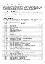
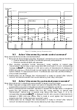
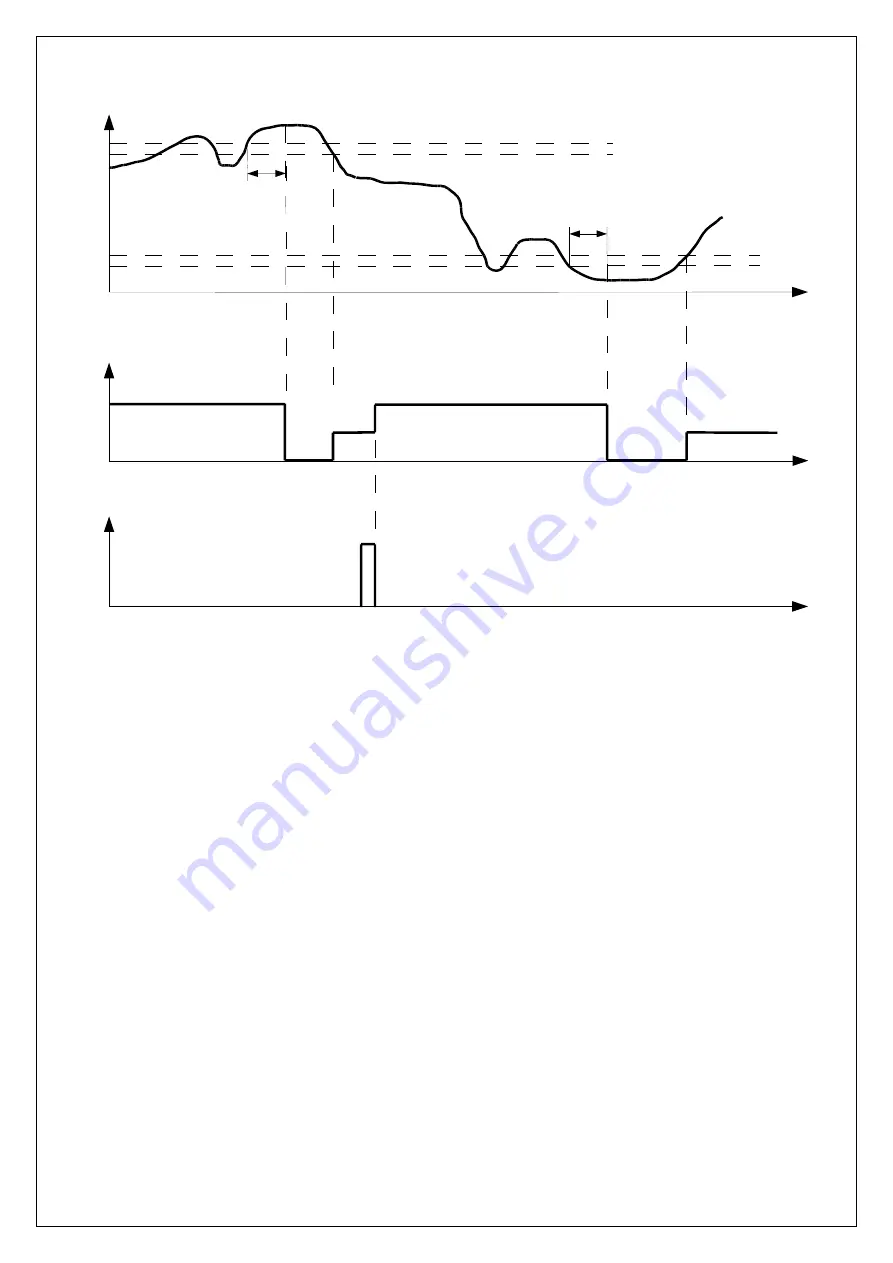
Figure 14-4 Relay control algorithm “swings of network voltage”
14.5 Action “allow to connect by remote control command”
Relay allow to connect by remote command workflow:
1. Relay can be allowed to connect by sending “allow to connect” command over any of these
interfaces:
•
Optical interface (IEC 62056-21 and DLMS protocols) with password;
•
Electrical interface (DLMS) with password.
2. After receiving command “allow to connect”, meter switches to internal state “ready to
connect”: internal relays remain open, relay state LED starts blinking and corresponding
message (
Load:SET
Load:SET
Load:SET
Load:SET
) is displayed on LCD and in OBIS code area a source of disconnection
is displayed (
....
....
....
....
). Entry is made to event register that “ready to connect” request came
from optical interface if it was received from it, if command was sent from electrical interface
– entry is made accordingly;
3. Internal relay can be reconnected after “connect” command is received from source allowed
by main relay control plan;
14.6 Action “allow to connect by end of billing period”
Relay allow to connect by end of billing period workflow:
1. Relay can be allowed to connect by end of billing period if disconnect reason was
“contractual power exceeded”.
2. When integration period is over, meter switches to “ready for reconnection” state: internal
relays remain open, relay state LED starts blinking and corresponding message (
Load:SET
Load:SET
Load:SET
Load:SET
)
is displayed on LCD and in OBIS code area a source of disconnection is displayed
Summary of Contents for G1B Series
Page 2: ......

