background image


SAFETY NOTICE 

Before applying power to the system, verify that the instrument is configured properly for the user’s 
particular application. 
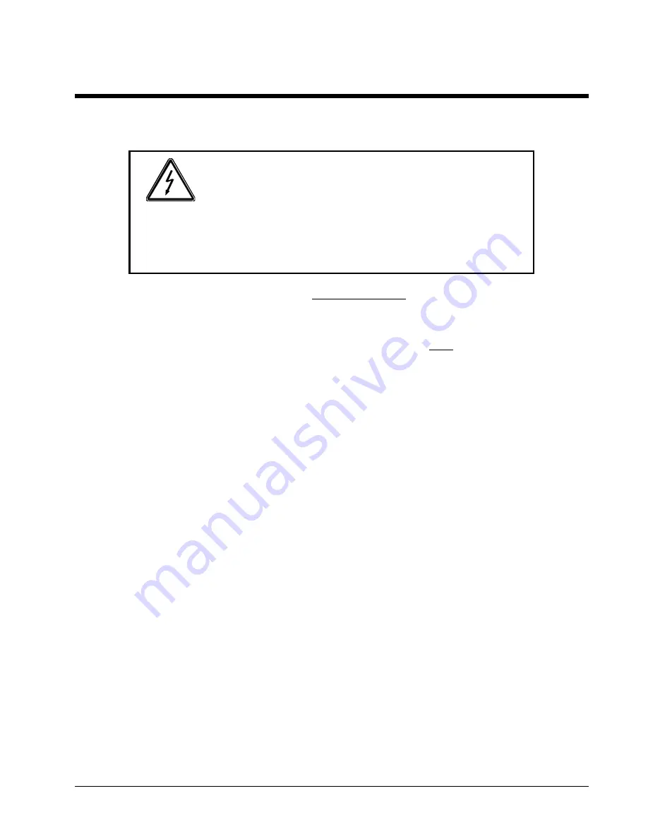


WARNING!


Hazardous voltages may be present when covers are removed. 
Qualified personnel must use extreme caution when servicing 
this equipment.  Circuit boards, test points, and output voltages 
also may be floating above (below) chassis ground.


Installation and servicing must be performed by qualified personnel who are aware of dealing properly 
with attendant hazards. This includes such simple tasks as fuse verification. 

Ensure that the AC power line ground is connected properly to the chassis.

 Similarly, other power 

ground lines including those to application and maintenance equipment must be grounded properly for 
both personnel and equipment safety. 

Always ensure that facility AC input power is de-energized prior to connecting or disconnecting any 
cable. 

In normal operation, the operator does not have access to hazardous voltages within the chassis. 
However, depending on the user’s application configuration, 

HIGH VOLTAGES HAZARDOUS TO 

HUMAN SAFETY

 may be normally generated on the output terminals. The customer/user must ensure 

that the output power lines are labeled properly as to the safety hazards and that any inadvertent 
contact with hazardous voltages is eliminated. 

Guard against risks of electrical shock during open cover checks by not touching any portion of the 
electrical circuits. Even when power is off, capacitors may retain an electrical charge. Use safety 
glasses during open cover checks to avoid personal injury by any sudden component failure. 

Due to filtering, the unit has high leakage current to the chassis. Therefore, it is essential to operate this 
unit with a safety ground.  

Some circuits are live even with the front panel switch turned off. Service, fuse verification, and 
connection of wiring to the chassis must be accomplished at least five minutes after power has been 
removed via external means; all circuits and/or terminals to be touched must be safety grounded to the 
chassis. 

These operating instructions form an integral part of the equipment and must be available to the 
operating personnel at all times. All the safety instructions and advice notes are to be followed. 

Neither Elgar Electronics Corporation, San Diego, California, USA, nor any of the subsidiary sales 
organizations can accept any responsibility for personnel, material or inconsequential injury, loss or 
damage that results from improper use of the equipment and accessories.  

iii 

Summary of Contents for CW 1251M

Page 1: ...els CW 801M CW 1251M CW 2501M 2002 by Elgar Electronics Corporation This document contains information proprietary to Elgar Electronics Corporation The information contained herein is not to be duplic...

Page 2: ......

Page 3: ......

Page 4: ......

Page 5: ...presentatives shall in no circumstance be liable for any direct indirect special penal or consequential loss or damage of any nature resulting from the malfunction of the product Remedies under this w...

Page 6: ...ii This page intentionally left blank...

Page 7: ...must ensure that the output power lines are labeled properly as to the safety hazards and that any inadvertent contact with hazardous voltages is eliminated Guard against risks of electrical shock du...

Page 8: ...sk of Electrical Shock CAUTION Refer to Accompanying Documents Off Supply Standby Supply On Supply Direct Current DC Alternating Three Phase Fuse Earth Ground Terminal Protective Conductor Terminal Cu...

Page 9: ...s 8 3 INSTALLATION 9 3 1 Unpacking 9 3 2 Wire Gauge Selection 10 3 3 Mounting Instructions 13 3 4 Cooling 13 3 5 Power In Connections 18 3 6 Power Out Connections 20 3 7 Sense Connections 21 3 8 Paral...

Page 10: ...15 Figure 3 4 Mounting Dimensions Top and Side Views CW 801M CW 1251M 16 Figure 3 5 Mounting Dimensions Top and Side Views CW 2501M 17 Figure 3 6 Input Power Connections 18 Figure 3 7 Output Power Con...

Page 11: ...l parallel cable A two speed fan results in quieter operation at lower power levels Key features of the CW Series AC power sources include High performance value design Output available at front or re...

Page 12: ...Elgar CW M Series This page intentionally left blank 2...

Page 13: ...0 5 100 Hz above 100 Hz AC Noise Level 50m VRMS typical for CW 801M and CW 1251M 100m VRMS typical for CW 2501M Amplitude Stability 0 1 of full scale over 8 hours at constant line load and temperatur...

Page 14: ...MS CW 1251M 0 to 18 6 ARMS CW 2501M Accuracy 2 of range for linear loads with current 0 2A for CW 801M and CW 1251M 0 4A for CW 2501M Resolution of Display 0 1A Frequency Range 45 to 500 Hz Accuracy 0...

Page 15: ...nt large green LED display Protection and Isolation Overvoltage Set screw adjustable Overcurrent 10 turn potentiometer Accuracy 2 of range for linear loads with current 0 2 A for CW801M and CW1251M 0...

Page 16: ...witches see Section 4 on page 25 Master or Slave field configuration Output disable enable at power up Overcurrent shutdown enable disable 2 6 Input Voltage and Frequency CW 801M 90 to 264 VAC 47 to 6...

Page 17: ...W 1251M 61 lbs 28 kg CW 2501M 94 lbs 43 kg Regulatory Compliance CE mark LVD EN61010 1 1993 Amendment 2 EMC EN55011 1991 Group 1 Class A EN50082 1 1992 Environmental Cooling Dual fan speed with side a...

Page 18: ...Elgar CW M Series 2 8 Options and Accessories L Locking knobs front panel potentiometers Rack Slide Kit Elgar part number K161570 01 Parallel Cable Elgar part number 890 497 40 8...

Page 19: ...arrier agent Perform a visual inspection of the instrument when it is removed from the shipping container Check for shipping damage such as dents scratches distortion and damaged connectors If damage...

Page 20: ...on properties are recommended for power source applications Avoid using published commercial utility wiring codes which are designed for the internal wiring of homes and buildings Although these codes...

Page 21: ...ngth Where Column 3 value Entry of the table above Cable length One way cable length in feet Vloss Maximum loss in volts permitted within cable Special case Should the Vloss requirement be very loose...

Page 22: ...d effects of The rated output voltage Transient voltages induced onto the conductors from any source The differential voltage to other nearby conductors and Safety margins to accommodate degradations...

Page 23: ...contains the appropriate slides and mounting brackets If you elect not to use slides mount the unit with standard support angles to sustain the weight of the unit in the rack Note that the front pane...

Page 24: ...Elgar CW M Series Figure 3 2 Mounting Dimensions Front and Rear Views CW 801M CW 1251M 14...

Page 25: ...Elgar CW M Series Figure 3 3 Mounting Dimensions Front and Rear Views CW 2501M 15...

Page 26: ...Elgar CW M Series Figure 3 4 Mounting Dimensions Top and Side Views CW 801M CW 1251M 16...

Page 27: ...Elgar CW M Series Figure 3 5 Mounting Dimensions Top and Side Views CW 2501M 17...

Page 28: ...er from the terminal block 2 Route the cables through the strain relief device Refer to Table 3 2 for cable recommendations 3 Connect SAFETY GROUND to the GROUND stud located next to the INPUT termina...

Page 29: ...not available connect LINE and NEUT across any of the phases 4 Reinstall the protective cover on the terminal block Tighten the strain relief device CW Model North American International CW 801M 18A...

Page 30: ...E to GROUND See Figure 3 7 below Most loads require NEUTRAL to be grounded The factory jumper may be removed if the load has a GROUND or if LINE or NEUTRAL voltages are held to less than 500 VRMS with...

Page 31: ...removed and the remote sense leads connected from the CW sense terminals to the load The point of voltage regulation will now be at the load and any voltage drop across the interconnecting output cab...

Page 32: ...inal block Twisted shielded leads for power and sense leads are recommended for the lowest noise operation If used shields should be connected to a CW output terminal block GND ground connector as sho...

Page 33: ...Master Unit To Slave Units INPUT LINE INPUT LINE INPUT GND INPUT GND INPUT NEUT INPUT NEUT OUTPUT LINE OUTPUT LINE OUTPUT NEUT OUTPUT NEUT Connect the master unit s sense leads either locally or to t...

Page 34: ...Elgar CW M Series This page intentionally left blank 24...

Page 35: ...4 1 CW Rear Panel 4 1 CONFIG Dipswitch The CONFIG dipswitch comes preset from the factory for stand alone operation With these settings the unit powers up to the current voltage and operates in const...

Page 36: ...urrent mode 8 OFF Current Shut off fault mode 9 12 Phase angle selections see Table 4 2 on page 31 Table 4 1 CONFIG Dipswitch Functions 4 2 Setting the CONFIG Dipswitch You may change the CONFIG dipsw...

Page 37: ...allel and Multiphase Configurations To operate parallel and or multiphase configurations set the switches cables and wiring as shown in the examples below 4 3 1 Setup for Three Phase Two Paralleled pe...

Page 38: ...Elgar CW M Series 4 3 2 Setup for Six in Parallel Configuration 28...

Page 39: ...Elgar CW M Series 4 3 3 Setup for Six Phase Configuration 29...

Page 40: ...Elgar CW M Series 4 3 4 Setup for Two Phase Configuration 30...

Page 41: ...table below Lagging Phase Angle Switch 9 Switch 10 Switch 11 Switch 12 A 0 ON ON ON ON 330 ON OFF ON ON 315 OFF ON ON ON 300 OFF OFF ON ON 270 ON ON ON OFF C 240 ON OFF ON OFF 225 OFF ON ON OFF 210 O...

Page 42: ...Elgar CW M Series This page intentionally left blank 32...

Page 43: ...USTER These five controls and indicators located on the left side of the front panel are used to select and display the power supply s output voltage V RANGE HIGH LOW Switch This switch allows you to...

Page 44: ...n slowly turn the adjustment counter clockwise until a fault is generated turning the output off p CURRENT FREQUENCY CLUSTER These six controls and indicators located in the center of the front panel...

Page 45: ...ill restore normal operation 5 1 Parallel and Multiphase Operation Follow the instructions in Section 3 8 Section 3 9 and Section 4 to set up paralleled or multiphase units Turn on the slaves prior to...

Page 46: ...on s front panel control setting The combined effect is full scale limited The impedance of the external analog control inputs is 10k ohms nominal Connect the voltage control signal to pin 1 Connect t...

Page 47: ...circuit boards 6 2 Fuse Replacement Replacement fuses for the CW Series supply are listed below in Table 6 1 Ref Designator Location Rating Manufacturer Mfr P N Elgar P N F1 F2 Motherboard 25A 250V T...

Page 48: ...Elgar CW M Series This page intentionally left blank 38...

Reviews: