background image

20


Caution: 

1. Do not use the work of inertia driving machine. 
2. Do not dig, do not push the bucket teeth into the ground using the inertia of the 
driving machine. This can overload the back of the machine and damage the drive 
track. 
3. Do not pull out completely the hydraulic cylinder piston rod. This results in a 
shortening of the life of the machine. Leaving to work as much as possible backlash. 
4. Do not use the work of inertia of the falling bucket. 
5. Do not dig by dropping the boom or bucket to use as a pick. Digging combined with 
stroke or continuous hitting can damage the operating system. 
6. Do not perform lifting. 


Caution! 

During work, always leave the support to the ground, so that the machine received 
appropriate support. 


Warning: 

Pay attention for diffrences in machines stabillity, depending on the angle of rotation 
of the body. 


5.6.


Transport  

While transporting the machine, follow the existing rules on weight, width, height, length and 
anchoring loads. 
Remove grease, oil, mud, ice, etc., from ramps or platform surface to prevent slipping off the 
machine. 

5.7.


Loading 

1. Turn on brakes of transporting vehicle 
2. Put blocks under the wheels of transporting vehicle 
3. Secure the ramps 
- check the strength, width, length and thickness of the plank ramps is sufficiently safe for loading, 

pay attention to the angle of ramps was 15 ⁰ or less.


4. Check that the left and right ramp are the same height. 
5. Ride slowly to the ramps. 
 

Summary of Contents for SpringerMAX-PRO

Page 1: ...Mini digger SpringerMAX PRO INSTRUCTION ...

Page 2: ...se to make it dangerous to be thoroughly familiar with the content of warnings and comments given in the instructions for the machinery Operators should carefully read all of this manual and observe all its recommendations Warning Do not operate the machine do not start work and do not perform any of the actions before reading the instructions for the machine Failure to follow these recommendation...

Page 3: ...ge Symbol draws attention to important informations 2 MACHINE FEATURES 2 1 General description The machine is designed for earthworks carried out in normal daylight conditions If the machine is to be used for other purposes or have to work in a potentially hazardous environment then follow the special safety regulations and the machine itself should be equipped according to the working conditions ...

Page 4: ...et changable equipment J Hydraulic pump K Overweight removable equipment 2 2 Technical data Engine Briggs Stratton XR2100 Engine power 13 HP Battery 12 V 24 Ah with electrolyte Hydraulic pump CASAPPA 8cc Hydraulic tank capacity 24 L Weigh 740 kg without counterweight Rotation 360 Maximum digging depth 1 65 m Noise No more than 85 dB A J K ...

Page 5: ...4 Important Detailed information about drive unit located in the Briggs Stratton engine manual ...

Page 6: ...5 PIC 2 MACHINES DIMENSIONS ...

Page 7: ...6 2 3 Equipment Grading bucket 70 cm wide Bucket 20cm wide Bucket 30cm wide Teeth ripper tool 2 4 Removable equipment Overweight 110 kg ...

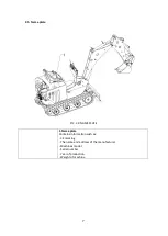
Page 8: ...7 2 5 Name plate PIC 2 3 NAME PLATE 1 Name plate Contains information such as CE marking The name and address of the manufacturer Machines model Serial number Year of production Weight of machine ...

Page 9: ... on Your own It is forbidden to use the machine in clothing unsuitable for this or another that can cause danger eg long dangling pieces of clothing It is forbidden to use the machine if the operator contamination with substances such as oil grease etc that may cause a slip hazard Warning Before operating the machine the operator of mini digger must have sufficient knowledge and read the instructi...

Page 10: ...rmation when using and operating the battery While use battery observe the safety instructions and relevant national regulations Before carrying out any battery operation including battery charging and starter battery use you should familiarize yourself with safe methods for working with batteries with an electrolyte Warning Batteries may emit explosive gases Do not smoke set fire or use high ener...

Page 11: ...status indicator is in yellow color or bright the battery s electrolyte level is below the top of the battery panel This can lead to personal injury Warning Do not allow the battery or the surrounding area to become contaminated with fuel or oil This can create fire hazards Warning Before cleaning the machine all electrical components must be protected against water and after drying dry them thoro...

Page 12: ... operator must read the instruction manual Warns against hot surfaces nearby engine and hydraulic pump Symbol draws attention to take special care in time staying close to working mini digger Symbol informs about the location where the hydraulic oil drain valve is located ...

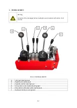
Page 13: ...xact location and function of all controls PIC 4 1 STEERING ELEMENTS A Left track steering lever B Right track steering lever C Support position steering lever D Arm position and rotation steering lever E Jib position and bucket work steering lever F Hydraulic hammer running lever ...

Page 14: ...stops the lever returns to this position automatically 2 backward in order to move track backwards push steering lever backwards B Pic 4 1 Moving forward Push forward both steering levers A and B Pic 4 1 machine will go forward Moving backward Pull back both steering levers A and B Pic 4 1 machine will go backward Turning left Push forward the right steering lever B Pic 4 1 the right track starts ...

Page 15: ...ck turning to the right Caution It is forbidden turning in opposite movement of the two tracks doing so may cause damage to the mini digger Support position steering C Pic 4 1 1 support lowering N neutral position support stops the lever returns to that position automatically 2 support lifting Arm position steering D Pic 4 1 N neutral position arm stay in neutral position 1 arm lifting 2 arm lower...

Page 16: ...neutral position 1 jib lowering 2 jib lifting 3 bucket closing 4 bucket opening Hydraulic hammer starting F PIC 4 1 1 moving the lever to the left activates the hydraulic hammer N neutral position jib and bucket stay in neutral position 5 USAGE 5 1 Before working N 2 3 4 4 1 N 1 ...

Page 17: ...afety Before starting the mini see if there is someone in her immediate vicinity Check for leaks Check for damaged or loose parts that could cause damage Check if there is fuel in the tank Check the hydraulic oil tank Check engine oil level Before driving check that the machine is not near other people When it is very cold do not direct the machine to work hard after starting Check battery mountin...

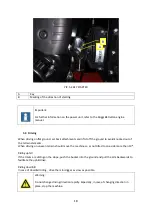
Page 18: ...17 RYS 5 1 ENGINE A Rope pulling holder B Fuel ignitation lever C Marking the position of the lever ...

Page 19: ...ut of the terrain elements When driving on uneven terrain should move the machine so as not tilted to one side more than 10 Riding uphill If the tracks are sliding on the slope push the bucket into the ground and pull the arm backwards to facilitate the uphill drive Riding downhill In case of downhill riding drive the mini digger as slow as possible Warning Do not change driving direction rapidly ...

Page 20: ...d tracks remove form the track accumulated soil recure the machine against the corrosion and thoroughly lubricate fill the fuel tank and oil to the maximum shut off the fuel supply to the engine according to the recommendations in the engine manual 5 5 Bucket working Mini digger is a multi purpose machine that can be equipped with a variety of specialized work equipment in order to perform many ty...

Page 21: ...form lifting Caution During work always leave the support to the ground so that the machine received appropriate support Warning Pay attention for diffrences in machines stabillity depending on the angle of rotation of the body 5 6 Transport While transporting the machine follow the existing rules on weight width height length and anchoring loads Remove grease oil mud ice etc from ramps or platfor...

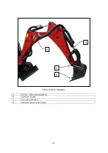
Page 22: ...et and gloves 1 Place the machine on a flat sturdy and level ground 2 Lower the light fixture to touch the ground 3 Stop the engine 4 Remove the bolts securing the mounting equipment to the jib and the jib cylinder 5 Remove the bolts and remove the equipment Important Keep pins clean Warning Do not put your fingers into the holes in order to verify their concentricity it can lead to serious accide...

Page 23: ...22 RYS 5 2 BUCKET CHANGING A Bucket removable equipment B Hydraulic cylinder C Pins with protection D Hydraulic quick connect nipple A B C D ...

Page 24: ... OF HYDRAULIC HAMMER 5 9 1 The hydraulic hammer Atlas Copco SB52 is mounted in place of the bucket pic 5 9 1 PIC 5 9 1 5 9 2 To use the hydraulic breaker connect the hydraulic hoses and connect with quick couplings PIC 5 9 2 A B A B ...

Page 25: ...of the hammer cannot be longer than 15 seconds when the material does not want to break change the place of impact ALL DETAILED INFORMATION ARE INCLUDED IN HYDRAULIC HAMMER OWNERS MANUAL 6 SERVICE Warning A person who does not apply to the safety instructions and who ignore included warnings must be sure that its approach work is safe 6 1 Service position Warning If you need to start working on th...

Page 26: ... and the correct equipment When draining emptying avoid spilling oil Oil spilled on the ground will harm the environment and can cause fire To work with the machine not to assume too loose clothing or jewelry that could get into the machine and cause damage Whenever required by your work wear personal protective equipment PIC 6 1 POINTS OF LUBRICATION AND OIL REPLENISHMENT ...

Page 27: ... Replenishment and changing of engine oil 6 2 Hydraulic oil replenishment Take care of proper hydraulic oil level The tank is located under the driver s seat and has got 24 liters of hydraulic oil PIC 6 2 HYDRAULIC OIL REPLENISHMENT A Hydraulic oil filler cap B Oil tank cap A B ...

Page 28: ...46 or other with the same parameters norm ISO L HV and DIN 51524 t 3 HVLP 6 4 Hydraulic cylinders and pins lubcrication All points where parts are in move must be properly lubricated Below there is exepmplary lubrication point All these points are equipped with grease nipples It is required to lubricate every time before working PIC 6 4 POINT OF LUBRICATION A Grease nipple 6 5 Hydraulic pressure c...

Page 29: ...h or too little strained Doing so may destroy them Tracks tension should be checked every time before working In case of too low tracks tension it is necessary to adjust it by using the adjustment screws on both sides of the mini digger To tension rubber tracks first loosen support screws on sides of bracket A than regulate the tension by regulation screws B A ...

Page 30: ...N REGULATION A Bracket screws B Regulation screws 6 7 Brass pins changing In the case of use of the brass pins replace them with new ones Knock out the pins out of the nest and embed new PIC 6 7 BRASS PINS A Brass pins B A B A ...

Page 31: ... The valve is used when operating the hydraulic pump and preventing oil spills after disconnecting the hydraulic hose PIC 6 8 TANK VALVE A Hydraulic oil tank valve Warning During operation the valve should always be in the open position otherwise it may cause damage to the hydraulic pump The valve should be closed only during the work related hydraulic pump and while transportng the machine 6 9 Ba...

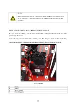
Page 32: ... engine under the operators seat The replacement should begin with the disconnection of the black mass lead Then disconnect the positive cable in red Loosen the wing screws and remove the retaining plate After this you can remove the used battery Install the new battery in reverse order paying particular attention to its secure mounting PIC 6 9 BATTERY A Battery B Cables C Wing screws D Retaining ...

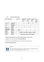
Page 33: ...ck x Change Replace in case of holes in isolations or brokes Hydraulic hoses Check x Change Replace in case of leaks or braid is visible X 1 Empty the tank when the oil filter is not heavily soiled you can use it again Mini digger is filled up with hydraulic oil AGIP ENI ARNICA 46 To next fill up it is recommended the same oil or other with the same parameters ISO L HV and DIN 51524 t 3 HVLP Impor...

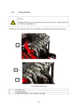
Page 34: ... at the factory Adjustment should be made only in justified cases The pressure in the hydraulic system can be throttled by a throttle valve at hydraulic distributor PIC 6 9 THROTTLING VALVE A Throttling valve 1 Loosen the lock nut 2 To throttle the pressure turn the valve to the right A 2 1 ...

Page 35: ...34 7 SPARE PARTS When ordering spare parts always state the information on the name plate of the machine or enter the symbol of the part ...

Page 36: ...y the manufacturer can be removed only at the expense of the user 6 If the above mentioned causes have caused permanent changes in the quality unit granted the guarantee expires 7 Machine repairing made during the warranty period by persons not authorized by the manufacturer will void the warranty 8 Warranty does not cover direct and indirect losses caused by defective machine 9 The warranty card ...

Page 37: ...o compile the technical file Owner Andrzej Zieliński The undersigned hereby declares that the product TRADE MARK MINI DIGGER SpringerMAX PRO FUNCTION MULTIFUNCTIONAL MINI DIGGER TYPE MODEL SpringerMAX PRO complies with the following European directives machinery directive 2006 42 WE of 17 05 2006 Dz U L 157 z 9 06 2006 page 24 and its amendment 2009 127 WE of 21 10 2009 Dz U L 310 z 25 11 2009 pag...

Reviews: