Installation and First Start-Up
- 18 -
7.5.3
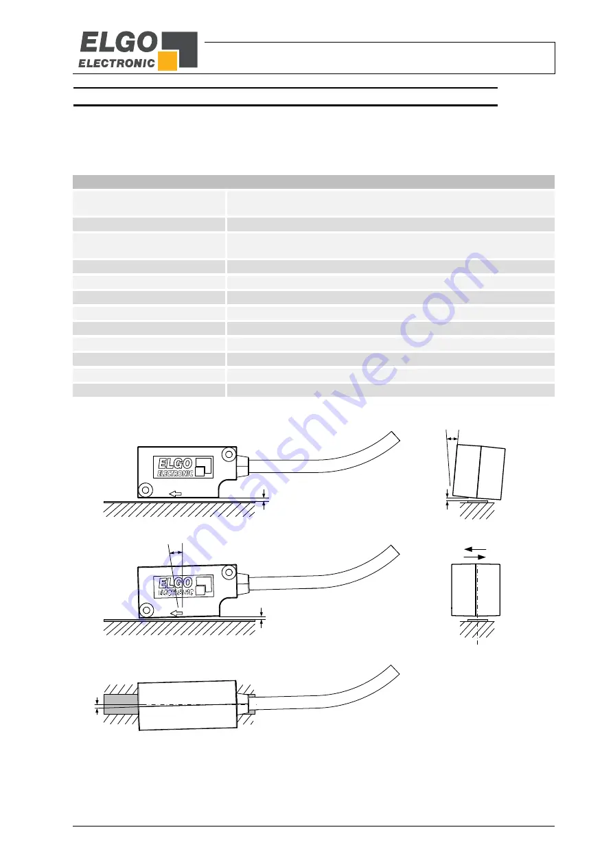
Mounting Tolerances
The mounting tolerances listed below apply equally to FMAX2 and FMAX3. The figures below are shown with
magnetic tape. However, the tolerances for the angles “Tilt”, “Pitch” and “Yaw” apply regardless of whether a
magnetic tape or a magnetic ring is used.
Table 2: Mounting tolerances
Tolerances
Required magnetic tape FMXA2
AB20-15-10-2-R or
AB20-15-10-2-R-D (without cover tape)
Required magnetic ring FMXA2
MRR-00-061-050-006-0128
Required magnetic tape FMXA3
AB20-20-10-2-R or
AB20-20-10-2-R-D (without cover tape)
Required magnetic ring FMXA3
MRR-00-080-072-007-0128
Reading distance sensor / tape
0.3 mm (resp. 0.6 mm when using without cover tape)
Reading distance sensor / ring
0.6 mm
Tilt angle for tape and ring
the max. permissible reading distance must not be exceeded at any position
Pitch angle for tape and ring
the max. permissible reading distance must not be exceeded at any position
Lateral offset with magnetic tape ±0.5 mm
Lateral offset with magnetic ring
±0.25 mm
Cross offset with magnetic ring
±0.1 mm (see drawing in section
Yaw angle for tape and ring
±1,5 °
Figure 9: Mounting tolerances sensor
Tape: ±0.5 mm
Ring: ±0.25 mm
Reading distance:
Tilt angle:
Pitch angle:
Lateral offset:
Yaw angle:
10
max. 0.3 mm
bzw. 0.6 mm
±1.5°
max. 0.3 mm
bzw. 0.6 mm
max. 0.3 mm
bzw. 0.6 mm
Summary of Contents for FMAX2 Series
Page 25: ... 25 Notes ...
Page 26: ... 26 Notes ...


