Installation and First Start-Up
- 28 -
10.4.3
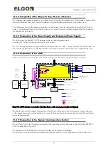
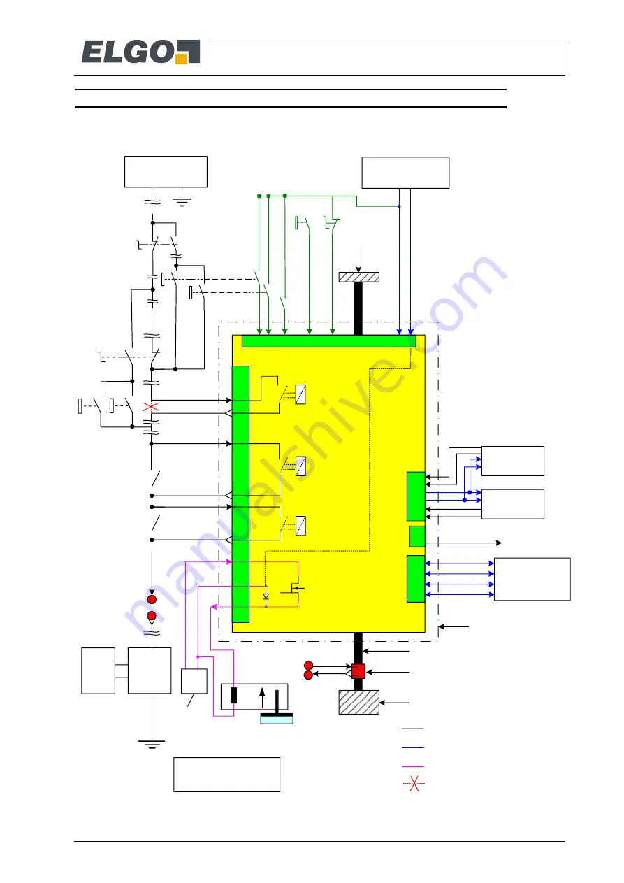
Overview of the Integration in the Lift Installation
on the next pages shows the circuit diagrams to connect the single wires of the
PIO and SCA cable
due to their functions to the elevator system.
Figure 8: Installation circuit diagram of LIMAX33 CP-00 (maximum configuration)
Weight and swing protection
Magnetic Tape
AB20-80-10-1-R-D-15BK80
1
2
Upper
fixation
1
to
presence
detector
from
presence
detector
Presence detector
LIMAX33CP-00
CAN HIGH
CAN LOW
CAN GND
CAN-H
CAN-L
SHLD
System boundary of
LIMAX33CP
Lift Control
Brake
2
SR1-O
OC *)
front doors
SR1-I
OC-O
OC-I
Recall
DOWN
Recall
UP
Recall
AC supply of
Safety circuit
Main
contactors
Safety circuit
Supply CAN
Safety gear supply
Cut safety circuit
Power supply CP 24VDC
(buffered if necessary)
rear doors
eSGC *)
Relase
safety
gear
Rail
This is only a symbolic drawing!
The safety gear itself is not part
of the certification
SR 1*)
SR 2 *)
SR2-O
BAT+ BAT- 24V GND
CAN-G
shield
SR2-I
Floor sensor 1
Floor sensor 2
12V-O
GND-O
SWS1-1
SWS1-2
SWS2-1
SWS2-2
Inspecti on
DOWN
Inspecti on
UP
Inspecti on
swi tch
DZO
DZO
UP DOWN
„EN81-21"
cont ac t
81-21 RESET WKP
RESET
BUTTO N
„Working
Platform“
Swit ch
24V
GND
SG_POW
SG_OUT
SG_GND
Internal connection
24V
(SGC)
GND
(SGC)
May be the
same like power
supply CP
*) Only symbolic, acullay
the actuatory consists
of 2 relays resp. FET’s plus
additional dianostics
External
Supply
SGC
Summary of Contents for LIMAX33 CP-00 SERIES
Page 91: ...91 Notes...


